
|
This task explains creation of a deck transverse stiffener with limits.
The image below shows a transverse stiffener (highlighted) placed on a
deck. 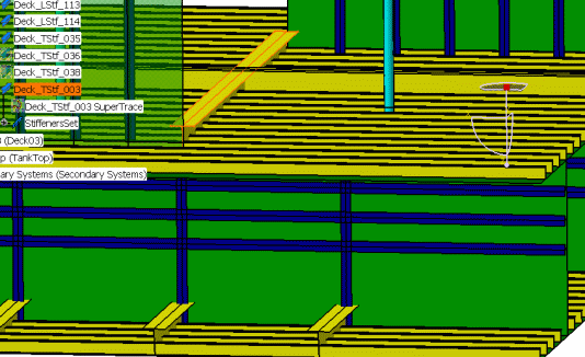
|

|
1. |
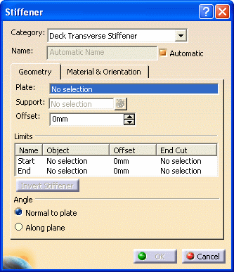
With your
document open, click the Stiffener button
 to open the
Stiffener dialog box. If you select the plate on which you want to
place the stiffener before you open the dialog box it will be pre-selected.
You can change the selection by clicking in the Plate field and
selecting a plate in the specifications tree, or in the viewer. to open the
Stiffener dialog box. If you select the plate on which you want to
place the stiffener before you open the dialog box it will be pre-selected.
You can change the selection by clicking in the Plate field and
selecting a plate in the specifications tree, or in the viewer.
 |
| |
2. |
Category:
Select a category by clicking the down arrow in the Category
field. The last 10 categories you selected will be displayed. If the deck
transverse stiffener is not displayed then click More to display
the Class Browser and make your selection. |
| |
3. |
Name: The
application can assign a name to the object you are creating using the
object naming
function if you check the Automatic checkbox. If you want to
assign your own name then uncheck the box and enter a name. |
| |
4. |
Support: Select
a support. Click in the Support field if it is not selected,
then select a support. The support will define a 'trace' on the plate,
which the stiffener will follow when it is placed. You can select any of
the following:
- Plane
- A surface that intersects the plate - you can
create your own surface if you need to
- Grid
The stiffener is placed when you select a support.
For transverse stiffeners, the supports are frequently defined from a
grid. The image below shows a grid and the deck on which the stiffeners
will be placed.
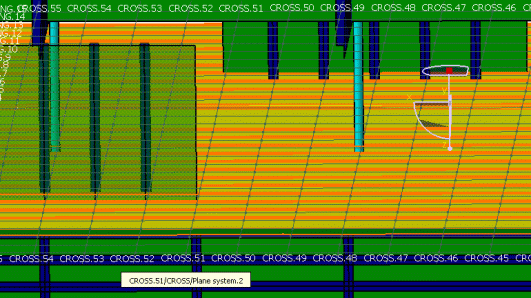
Click the button next to the Support field
to display the Elements List. You can use the list to delete or
replace supports that you have added. To replace, select the support, click
the Replace button, then select the new support. |
| |
5. |
Offset: Enter a
value in the Offset field if you need it. This is the value by
which the stiffener will be offset from the support you selected. The value
is expressed in the units selected in your workbench. Enter a negative (-)
sign in front of the value to offset it in the opposite direction. |
| |
6. |
Limits: By
default stiffeners are placed from end to end of the plate you selected. If
you need to resize a stiffener then you have to define the limits.
Under Limits, in the
Name field, select Start and select a starting
limit. You can select a plane, plate, another stiffener or a surface. The
stiffener is limited as soon as you make your selection.
Use the same method to define the End. The
images below show a stiffener that has not been limited, and one that has
been limited.
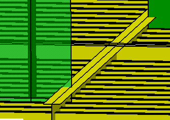
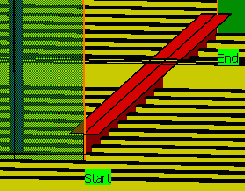
Under Offset, you can define the offset value of each
stiffener limit. |
| |
7. |
Invert Stiffener:
The
Invert Stiffener button becomes available when you have defined one
limit - start or end. Clicking this button inverts the stiffener limit in a
toggling action. |
| |
8. |
Angle: To
place the web of a stiffener at an angle, make sure the support object
you select (plane, surface) is at an angle, and select the
Along Plane option. The stiffener is placed at that angle. The default
angle is the last one used.
NOTE: When creating a stiffener using a curve as a support, the Along Plane
angle has no effect.
Use the Normal to Plate option. |


