to make sure that they are perfectly continuous.
This task shows how to improve a node of the network to this purpose:
- the action modifies a set of curves arriving at a same node so that
they have the same extremity
(G0 continuity) and the same tangent plane at this node (G1 continuity). - this ensures that all surfaces built on each mesh arriving at this node are continuous in tangency.
The curves may be simple curves, 3D curves, face edges...
Curves are deformed :
- to be made G0 continuous (passage continuity) in all cases,
- to be made G1 continuous (tangency continuity) according to your needs
(for example, you do not want to apply a tangency continuity constraint on a sharp edge).
It is also possible to make two curves tangent to each other.
Only the curves constrained to the tangent plane are made tangent to each
other.
The curves set to Continuous only cannot be made tangent.
The G0 continuity can be tuned up using the Maximum deviation
parameter
i.e. the maximum distance between the input curve and the deformed curve.
The G1 continuity can be tuned up using the Max Angle G1
parameter,
below which curves are made tangent to each other.
- This action complies now with a feature-based approach.
- The result of Adjust Node feature is a multi-domain curve.
the deletion of one of its input curves may result in an update error for features
that use the adjusted node as input.
- Therefore standard selection tools, including the user selection
filter and the geometrical element filter,
can be used.
For further information, please refer to Selecting Using a Filter in the Infrastructure User's Guide. - After the creation of the result Adjust Node, all input curves are sent to the NoShow.
- It is possible to create datum curves (instead of the feature) by activating Create Datum in the "Tools" bar.
- Multi-domain and multi-edges elements are not accepted as input.
If you select such an element, the following messages are displayed requesting you
to select each sub-element separately by activating the Geometrical Element Filter of the User Selection Filter.

-
Define an In Work Object.
-
Click Adjust Nodes
 .
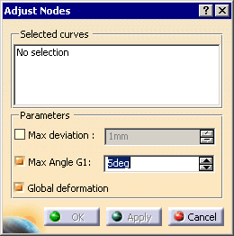
The Adjust Node dialog box is displayed.
By default, the check boxes Max Angle G1 and Global deformation are selected.
Their status and that of Max deviation are modal.
-
Select the curves to adjust. They are listed in the Selected Curves field.
You can deselect a curve by picking it, or select another curve.

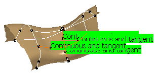
By default, the curves are "Continuous and tangent"
Click the label of a curve, or right-click to launch its contextual menu,
to change its status.
The available statuses are:
-
Continuous and tangent: the
deformed curves are G0 continuous and
tangent to the computed tangency plane. - Continuous: the deformed curves are only G0 continuous.
- Fixed: the curves are not deformed. In particular, face edges are fixed and remain fixed.
-
Continuous and tangent: the
deformed curves are G0 continuous and
-
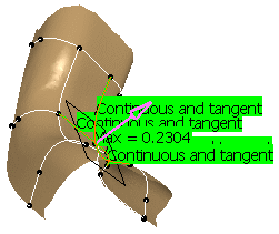
Click Apply. The deformations are computed:
- The curves selected are highlighted,
- The curves modified are displayed in green,
- If there are tangency constraints, the tangency plane is displayed in white,
- Its vector are displayed in pink,
The maximum deviation is also displayed on the most deformed curve,
not necessarily on that deformation spot.

The curves are deformed to reach the required continuity.
By default, the Global deformation check box is selected and distributes the deformation more evenly on the whole curves.
The degree and the structure of the curves are kept.
Clear this check box for a local deformation, meaning the curves are deformed at their extremities.The result may not be satisfactory. In that case, you can:
-
Select the Max deviation check box and
type the value of the maximum allowed deviation.
Click Apply, the deformation of the curves is computed and displayed.
If the deformation is greater than the requested tolerance, no adjusted node can be created.
You have to modify this tolerance. -
Make sure the Max Angle G1 check box is
selected to force a tangency constraint on the curve
endpoints when the angle of the tangents at those ends is lower than the Max Angle G1 value.
-
Click OK to validate the action. The Multi-Result Management dialog box is displayed.
Select the option you require and click OK.
-
Click OK to validate.
An Adjusted.Node.X feature is created in the specification tree, the input curves are hidden.

In Datum mode, x new curves are created while the x input curves are hidden.

- This action processes one node at a time.
- There must be more than one curve to adjust.
- Several non continuous fixed curves may lead to inconsistencies.
-
If some curves are deformed too far apart with respect to
the tolerance,
the adjustment cannot be computed and an error message is displayed.
![]()