-
Click Solid Combine
 .
.
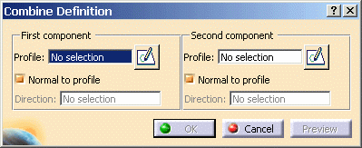
The Combine Definition dialog box appears.
-
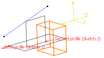
Select Sketch.1 as the first component to be extruded.
Sketches must contain closed profiles. Note that if you launch the Solid Combine command with no profile previously defined, just access the Sketcher by clicking the icon available in the dialog box and sketch the profile you need.
Components
The components you can select are:
- Sketches
- Surfaces
- Sketches sub-elements: for this, use the Go to Profile definition contextual command. (for more information, refer to Using the Sub-elements of a Sketch)
- 3D planar curves
- A sketch containing more than one domains cannot be selected for creating solid combine features.
- A sketch containing closed mono-domain or a single domain of multi-domain sketch (using go to profile command) should be used to create Solid combine features.
- If needed, you can change the component by clicking the Profile field and by selecting another sketch in the geometry or in the specification tree.
-
You can also use any of these creation contextual commands available from the Profile field:
-
Create Sketch: launches the Sketcher after selecting any plane, and lets you sketch the profile you need as explained in the Sketcher User's Guide.
-
Create Join: joins surfaces or curves. See Joining Surfaces or Curves.
-
Create Extract: generates separate elements from non-connex sub-elements. See Extracting Geometry.
-
-
Select Sketch.2 as the second component to be extruded. This sketch contains only one profile, namely a rectangle.
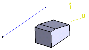
The Solid Combine capability computes the intersection between the profiles virtually extruded. By default, each component is extruded in a plane normal to its sketch plane. The application previews the result as soon as the second component has been selected.
Extrusion Directions
There are two types of directions you can specify to compute the intersection. For the first and the second components, you can choose:
- The Normal to profile option: this is the default option
- Another direction indicated by a geometrical element you select.
-
For the purposes of our scenario, uncheck the Normal to profile option for the first component and select the line created in Sketch.3 to indicate the extrusion direction.


-
Click OK to confirm and create the solid combine feature.
The new element (identified as Combine.xxx) is added to the specification tree.