 |
This task shows you how to create
and edit gates along a parting line on the mold
base. |
 |
There are several restrictions concerning the manipulation
(notably when copying, pasting, deleting, dragging and dropping) of
components and drilled CATParts. Click here
for more information. |
 |
You can create one or several
gates, either:
- on the parting line (recommended), or
- directly on the molded part (using existing 3D points or vertices,
...).
|
 |
-
Open file
MoldWithMoldedPartAndComponents.CATPoduct in the sample/MoldAndPart
directory.
-
Hide Mold1 in the specification tree (this is
not obligatory but makes it easier to demonstrate point selection).
-
Click Add Gate
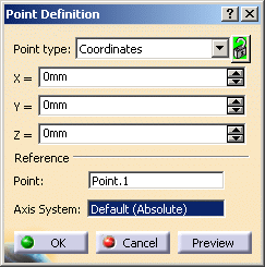
 . The point definition dialog box
is displayed. . The point definition dialog box
is displayed.
-
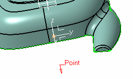
Select a point on the molded part to define the position
of the gate. Click OK.
-
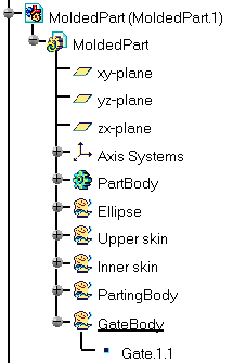
A GateBody and a Gate.1.1 point are
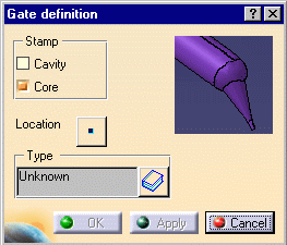
created in the specification tree and the gate definition dialog box is
displayed.
-
Use Stamp to create
the gate either in the cavity and/or in the core.
-
Location: click
the point icon to modify the position of the gate.
-
Click the catalog browser icon
 to define the type of the
gate: Side,
Direct or
Submarine. to define the type of the
gate: Side,
Direct or
Submarine.
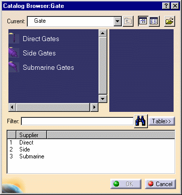
-
Click
 in the
dialog box and browse to the location of the catalog of your choice. You
can use your own catalog. in the
dialog box and browse to the location of the catalog of your choice. You
can use your own catalog.
-
Double-click Type to select the
section shape: Round, Rectangular,
Conic or Cylindrical.
Then adjust the parameter values accordingly. The type of section you can
use depends on the type of gate you have selected.
Direct Type
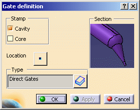 |
|
Side Type, Round section
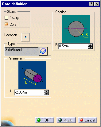 |
Section R -
Radius
Parameter
L - Length
|
Side Type, Rectangular Section
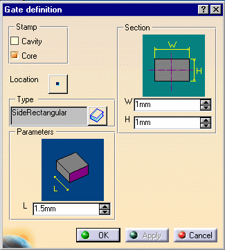 |
Section
Parameters
|
Submarine Type, Cylindrical
Section
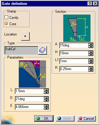
|
Section
Parameters
|
Submarine Type, Conic Section
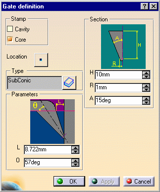 |
Section
- H - Height
- R - Radius
- A - Aperture angle
Parameters
- Q - Gate angle slant
- L - Distance between the gate and the cavity measured on the
parting surface (this parameter is computed from the others and you
cannot modify it)
|
Submarine Type, Round Section
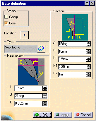 |
Section
- A - Aperture angle
- H - Height
- L1 - Length
- R1 - Radius of the cylindrical nozzle
- R2 - fillet radius
Parameters
- L - Distance between the gate and the cavity measured on the
parting surface
- Q - Gate angle slant
- E - Minimum length of the cylindrical nozzle (this parameter is
computed from the others and you cannot modify it)
|
|
|
|
|
-
Select a gate point in the specification tree, then
Gate Edition from the contextual menu of the object.
The Gate definition dialog box is displayed. You can now modify
the location of the gate.
|
 |
You must not change the names of gates once you have created them. |
|
|
| |
-
Activate the MoldedPart.
-
Right-click a gate in the viewer or the tree and select
Delete in the contextual menu to delete the gate.
|
|
 |
![]()