Structure of a component
To obtain a good result when inserting user components in a Mold Tooling Design project, it is important to follow some rules detailed hereafter.
- A Mold Tooling Design component can be a CATPart or a CATProduct, which may contain one or several CATPart that can be Mold Tooling Design components.
- The name of the CATPart or of the CATProduct must be the name of the user component that is also used in the catalog (here WearPlate_Z15W).
- A CATPart of a component is composed of:
Parameters

When you make a selection from a catalog, only parameters that have been used as keywords in the catalog will be displayed.
When you make a selection from a folder, no such filter can be applied. In this case, all visible parameters (i.e. that have not been defined as hidden) will be displayed.- We recommend that the Z+ axis of the component be oriented upwards (towards the injection side).
- Some parameters that can be associated to one or several design
tables. This is recommended if an object has several sets of
parameters. The names of the design tables are free.

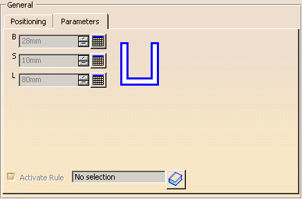
- Some of these parameters (e.g. B, S and L in the image below)
need to be accessed during the insertion/edition of the component:
they are displayed in the parameters tab of component dialog box.

- To allow this display, the name of the concerning parameters
must be put as
keywords in the corresponding catalog (B, S and L in the image
below).

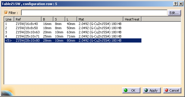
- Only one parameter named Ref (string) that represents
the supplier reference is mandatory. Its contents is displayed in
the Config/Reference field of the dialog box used to add
or edit a component

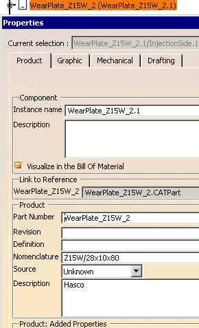
and copied to the Nomenclature field of the Product properties (useful for the Bill of Material) of the inserted user component.
- The names of the other parameters are free.
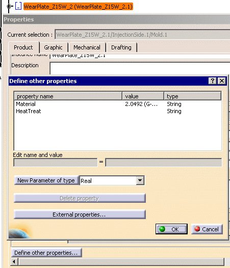
- For the Bill of Material, it is
also recommended to add some properties such as Material
and Heat Treat in the Product properties of
the CATPart of the component, using the Define other properties...
button. Standard components from Mold Tooling Design already contain
the added properties Material and HeatTreat.

When splitting a user component and in order to optimize memory usage, you can define a parameter, D_Split, that gives the diameter of a contour that is projected onto the splitting surface so that only the surface inside the contour (and not the whole surface) will be used to split the component. Bodies
- The PartBody that contains the geometry of the component. It may consist of pads, sketches, technological results etc. The name of the PartBody is free.
- A body named BaseBody that contains a point named Base to locate the component when it is inserted in the mold. In case of assembled component (a CATProduct), the Base point of the first CATPart is taken into account for the location.
- If needed, a body with a name that starts with DrillHole
that contains the definition of the associated drilled holes that
are removed in the elements defined through the Drill From/To
function of the component dialog box.
There may be several of these and we recommend that you insert as many as necessary for your machining strategy (to differentiate, for instance, the holes that were in the original part to machine and the holes that you wish to insert). - If needed, a body with a name that starts with TapHole
that contains the definition of the associated threaded holes that
are removed in the element defined through the Drill To function of
the component dialog box (this element is the latest of the list).

- Pads can be used to add material around a component. Give the body a name that begins with Pad , e.g.PadForContouring. We recommend that you choose names that indicate the final purpose of the pad or pocket as there may be several in a user component.
- Pockets can be used to remove material around a component. Give the body a name that begins with Pocket e.g.PocketForMilling. We recommend that you choose names that indicate the final purpose of the pad or pocket as there may be several in a user component.

Pads and pockets are only applied to the element defined in the DrillFrom field of the Define Component dialog box.
![]()