Design Changes and Associativity Mechanisms
This section deals with design changes and the various
associativity mechanisms provided with Machining products.
| For information about... |
Please refer to... |
|
Methodology for Design Changes. |
|
| Status for operation creation and
modification, Geometry not up to date, Geometry not found, tool path
status, and so on. |
Product Behavior for Design
Changes |
Methodology for Design Change
The following example illustrates the methodology for
Design/Manufacturing reconciliation after a design change.
Consider a Part Operation which references a CATProduct
(Product1), which in turn references a CATPart (Part1).
Product.1, which is the component visible to the user in the
interactive session, is stored in the document Product1.CATProduct.
Part.1, which is the component visible to the user in the
interactive session, is stored in the document Part1.CATPart.
In order to modify the design of the CATPart proceed as
follows.
Preparation Before Design/Manufacturing
Reconciliation
-
Modify the design in Part1.
-
Save Part1 as Part2 (rename Part1.CATPart as Part2.CATPart).
-
Open Product1.
-
Replace the component Part1 by Part2.
-
Save Product1 as Product2 (rename Product1.CATProduct as
Product2.CATProduct).
Note that component instance names of Product1 should be unique
and they should be identical to the component instance names of Product2.
Product part numbers may be different.
Then there are two ways for reconciliation of the design and
manufacturing:
Design/Manufacturing Reconciliation by Direct
Selection using the Part Operation Editor
-
Open the CATProcess.
-
Edit the Part Operation that references the old design. Click
Product or Part
 in the Part Operation dialog box and select the new product.
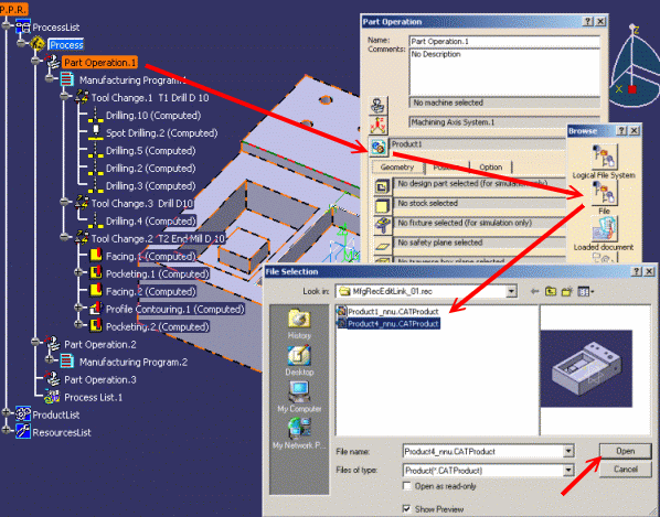
-
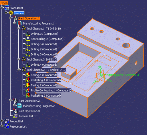
Click OK to quit the Part Operation dialog box. The various
machining operations are updated.
Notes
-
Depending on the document environment setting (Tools
> Options > General > Document tab), the new product can be selected from a
file, a catalog, and so on.
-
The impacts of the reconciliation are global with respect to
the CATProcess and not local to the Part Operation. This means that all the
Part Operations that referenced the old design will now reference the new
design.
Design/Manufacturing Reconciliation by Edit
Links
-
Select Edit > Links.
-
In the Links tab, select the line corresponding to the link
of the Part Operation that references the old design, then click the
Replace button.
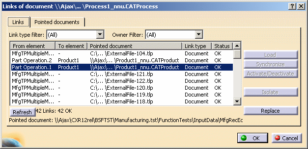
Notes
-
Depending on the document environment setting (Tools
> Options > General > Document tab), the new product can be selected from a
file, a catalog, and so on.
-
You must use the Links tab to replace the old
design. Do not use the Pointed Documents tab to do this.
-
You must not do a Replace on the line corresponding to the
Product > CATProduct link. This link is not managed by Machining products and
so cannot be used in design/manufacturing reconciliation.
-
The impacts of the reconciliation are global with respect to
the CATProcess and not local to the Part Operation. This means that all the
Part Operations that referenced the old design will now reference the new
design.
More About Associativity in Machining Documents
In case of design changes, the designer provides the NC
programmer with one or more new CATParts and CATProducts. The programmer has to
replace the old CATProduct referenced by the CATProcess by a new one including
the new CATParts and CATProducts. As described in the previous chapter, the
programmer can use either the Edit Links capability or the Part Operation
editor for this.
A CATProcess can be linked to CATProduct/CATPart in several
ways:
-
There are links between Part Operation and the CATProduct
containing the geometry to be machined.
-
There are links between operations and the geometry to be
machined contained in the different CATParts/CATProducts included in the
CATProduct linked to the Part Operation.
-
There are links between formulas used by the operations and
CATParts/CATProducts included in the CATProduct linked to the Part Operation
through the formula parameters.
When a design referenced by the CATProcess is modified, the NC
programmer has to reconcile the CATProcess with the new CATProduct using the
Edit Links capability.
After reconciliation using the Edit Links capability:
-
The new CATProduct should appear in the ProductList and be
linked to each Part Operation that was linked to the old one.
-
Each operation that pointed a geometry that was included in
the old CATProduct:
-
should now be linked to the equivalent geometry in the new
CATProduct if it exists
-
or be in Geometry not found status, if the
equivalent is not found in the new CATProduct.
-
Each formula that referenced an element of a CATPart of the
old CATProduct, should now reference the equivalent element in the new
CATProduct.
That is, if a formula points to parameters that are defined
in the CATProduct you want to replace, after reconciliation the formula will
point to the corresponding parameters in the new CATProduct.
If some of these parameters are not found, the behavior will
be the same as when a parameter is deleted. A clone of the parameter will be
aggregated under the formula. It will take the value of the old parameter and
becomes fixed. The formula will be not broken and will continue to be
associative with the other parameters.
Note that this rerouting is possible only if the new CATParts
and CATProducts are created by a Save As of the old ones. The instance
names in the new CATProduct must be the same as in the old CATProduct.
Associativity and Publication
in Machining Documents
All links on published geometric elements can be retrieved
using the Edit Links capability or the Part Operation editor even when the
replaced part is new compared to the previous one. This means that
associativity is assured in design change scenarios even when CATProduct/CATPart
B is a New From of CATProduct/CATPart A.
Consider the following scenario where the NC programmer
receives a CATProduct, in which some geometric elements have been published.
The programmer defines the process by selecting either the
published elements in the specification tree or the geometry in the geometry
visualization area.
The publication name of the published reference geometry is
displayed in the Geometry Analyser dialog box. This enables the programmer to
be sure that the selected geometry has been published.
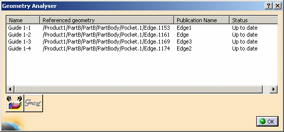
The NC programmer receives a new version of this CATProduct. To
reconcile the original CATProcess with this new version, the programmer can use
the Edit Links capability or modify the CATProduct using the Part Operation
editor.
To be sure there are no positioning problems in the old and new
CATProducts, each instance corresponding to an old one should have the same
instance name.
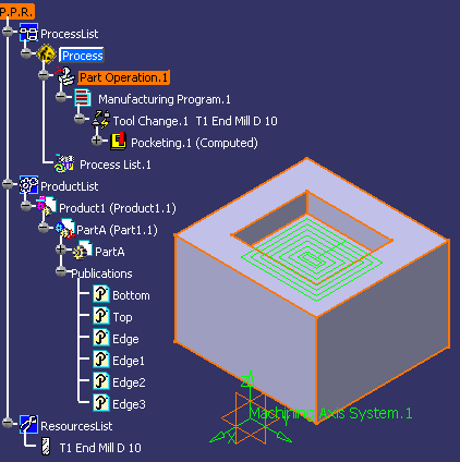
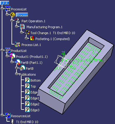
Then the NC programmer must select the new CATProduct.
For each operation pointing to published geometry, the system
searches for the same publication name in the corresponding product instance
(same instance name). If the corresponding publication is found, the operation
will be rerouted to the new geometry.
Manual rerouting is proposed for publications that have not
been solved automatically in the following dialog box.
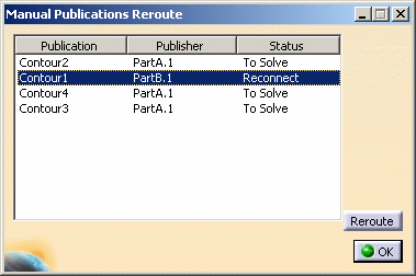
The NC programmer must select the new publication in the new
CATProduct inserted the ProductList that corresponds to the old publication.
In this case, all operations that pointed to the geometry under
the old publication will be rerouted to the geometry under the new one.
Publications that are not solved at this time will be lost and
operations that pointed to geometry in this old publication will be in
Geometry not found status.
The NC programmer obtains a new CATProcess with operations
whose status is Not up to date (or Geometry not found if some
selected geometry was not published or have no corresponding publications in
the new CATProduct). The programmer must then validate the reconciliation by
analyzing geometry and replaying the tool path.
Associativity and Publication for Axial
Machining Operations
Geometry in axial operations is defined by a machining pattern
and a geometrical feature. The geometrical feature is automatically linked to a
design geometry when the first position of the machining pattern is selected.
If this position is a design pattern, then the geometrical feature is linked to
the design pattern's reference.
An axial operation is geometrically complete when:
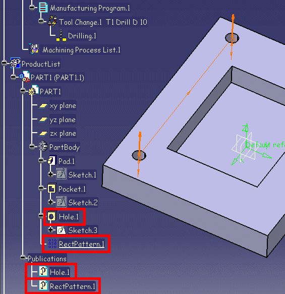
In the following example, Drilling.1 contains a machining
pattern whose referenced geometry is RectPattern.1. When RectPattern.1 is
selected, Hole.1 (reference of RectPattern.1) is linked to the geometrical
feature of Drilling.1.
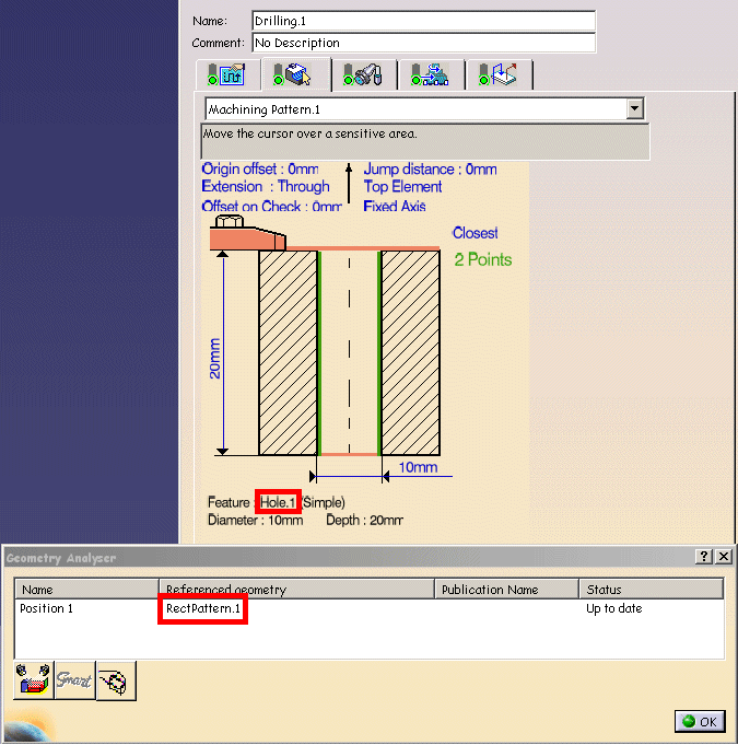
If you want to make a design change by replacing the Part or
Product in the Part Operation, both RectPattern.1 and Hole.1 must be published.
Then all geometrical links in the axial operation can be resolved.
Product Behavior for Design
Changes
The rules described below describe the various status of the
elements referenced by machining operations and how to recognize these status.
It deals with the following:
-
Status lights on machining operation tabs, for example
 .
.
-
Symbols used on the specification tree icons, for example
 .
.
-
Texts used in the specification tree, for example Computed.
Useful settings in
Tools > Options > Machining > General for tracking design changes are:
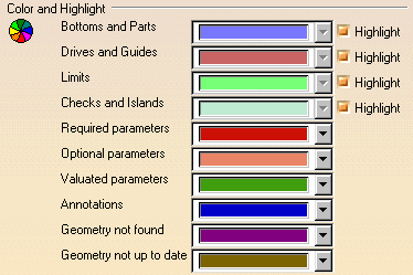
Operation Creation
Before selection, a required element is colored according to the color
setting for Required parameters. Once selected, it is colored according
to the color setting for Valuated parameters.
Before selection, an optional element is colored according to the color
setting for Optional parameters. Once selected, it is colored according
to the color setting for Valuated parameters.
The status light on a tab is Red when all the required elements of that tab
have not been selected. Once selected, the status light becomes Green.
The Replay is not available when the status light on a tab is Red.
After a successful Replay, the status of the operation becomes Computed.
Depending on the Machining product and/or type of operation, a tool path node
may be added to the computed operation in the specification tree.
Operation Modification
Once modified, a selected element is colored according to the color setting
for Geometry not up to date.
This allows quick recognition of impacted machining features.
The Analysis of the element is then possible: its status becomes Not up
to date. Its Smart Geometry is visible.
The status light of the corresponding tab is Orange.
In the specification tree, the operation icon has an Update symbol
 . If the operation had
Computed status, it remains in this state.
The Replay is available.
Selected Element No Longer Present
Once deleted (or no longer present), a selected element is colored according
to the color setting for Geometry not found. This allows quick
recognition of deleted machined geometry.
The Analysis of the element is then possible: its status becomes Not
found. Its Smart Geometry is visible.
The status light of the corresponding tab is Red.
In the specification tree, the operation icon has an Exclamation symbol
 . If the operation had
Computed status, it remains in this state.
The Replay is not available.
The status light of the corresponding tab becomes Green when all the
elements with the Geometry not found or Required parameters color
setting are:
- selected (they take the Valuated parameters color setting)
- or "removed" (they take the Optional parameters color setting).
The Replay is not available when the status light on a tab is Red.
Operation Status
An Update symbol  means that
at least one selected element has been modified. In the corresponding tab the
status color is Orange and the color setting is Geometry not up to date.
An Exclamation symbol  means one of the following:
- At least one selected element is no longer present. In the corresponding
tab the status color is Red and the color setting is Geometry not found.
- At least one required element has not been selected. In the corresponding
tab the status color is Red and the color setting is Required Geometry.
A Locked symbol
 means that a computed operation
and its tool path is in a Locked state. The OK button of the operation editor
is not available. This is the result of a deliberate user action and the
operation remains in this state until it is unlocked by the user.
Please refer to Lock/Unlock Mechanisms for more
information.
Status are obtained when Update Activity Status Automatically
is not set in
Tools > Options > Machining > General. To know the status of one, several
or all operations of a program, you must click Status of Selected
Activities
 in the Auxiliary Commands toolbar.
Note: Machining operations that were created just before a system
crash, are regenerated during Warm Start with status Not up to date.
Tool Path Status
The Computed text in the specification tree means that the operation
has been computed (that is, the tool path is present).
It does not guarantee the coherence of the operation with respect to the
context. Its coherence is guaranteed by a replay when this available.
When there is no text, this means that the operation has not been computed
(that is, the tool path is not present). This status is obtained after creating
an operation without a tool path replay or after removing a tool path.
![]() in the Part Operation dialog box and select the new product.
in the Part Operation dialog box and select the new product.


