|
|
This task shows you how to edit a tool that is already used in your document. | |
|
|
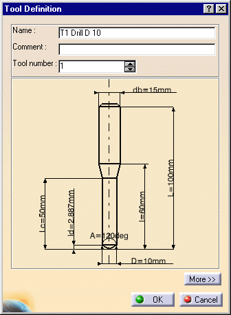
1. | To edit a tool in the resource list, right-click it and select Edit NC Resources. |
| The Tool Definition dialog box is displayed allowing you
to edit the tool's geometric, technological, cutting condition, and
compensation characteristics.
|
||
| 2. | If needed, enter a new name for the tool. You can also assign a comment. | |
| 3. | If needed, use the spinner to increment the Tool number. | |
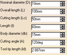
| 4. | Click More to expand the dialog box to access the Geometry, Technology, Feeds & Speeds, and Compensation tab pages. | |
| 5. | You can specify the tool geometry in two ways:
The icon representation of the tool is updated with these values. |
|
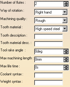
| 6. | Click the Technology tab and enter the
desired values for the tool's technological parameters. |
|
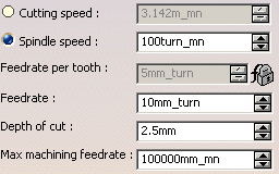
| 7. | Click the Feeds &
Speeds tab and enter the desired values for the tool's cutting
conditions. You can choose between Cutting speed (linear) or
Spindle speed (angular) value. |
|
|
|
Note 1:
For machining operations and associated tools handling finish or rough
parameters, the finishing rotation speed can now be a Finishing cutting speed
or a Finishing spindle speed and the roughing rotation speed can be a
Roughing cutting speed or a Roughing spindle speed.
Note 2: The units associated to each attribute are set using the Tools > Options > General > Parameters & Measure > Units tab page.
Cutting speed and spindle speed are related as follows (when tool diameter units are in mm):
See Feeds and Speeds for more information. Note 3: The Feedrate attribute used in previous releases is replaced by Feedrate per tooth. The Feedrate attribute represents the global feedrate of the tool. If you modify global Feedrate, the Feedrate per tooth is updated according to the formula:
Feedrate per tooth cannot be edited directly in the Feeds & Speeds tab. |
|
| 8. | If tool compensation is required, click the
Compensation tab.
You can either edit an existing compensation site or add another site, if other sites are proposed. See Specify Tool Compensation for more information.
See Specify Tool Compensation for more information. |
|
| 9. | Click OK to accept the modifications made to the tool. | |
|
|
A CATPart or CATProduct
representation can be assigned to the tool by right-clicking the tool
node in the Resource List and selecting NC Resources > Add User
Representation.
When a Photo or Video simulation is done, the CATPart is searched for sketches representing the profiles of cutting and non-cutting parts of the tool. Please refer to user-defined tool profiles in simulation for the rules for defining these profiles. |
|
|
|
||
