This section deals with the material removal simulation capability provided with the Replay Tool Path command.
| For information about... | Please refer to... |
| CATProduct user representation of tools | |
|
CATPart tools for milling |
CATPart Tools for Photo or Video Mode |
| Stock considerations |
You can attach a CATProduct to a tool or tool assembly by means of the NC Resources > Add User Representation contextual command in the Resource List.
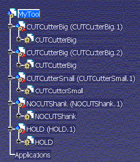
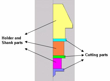
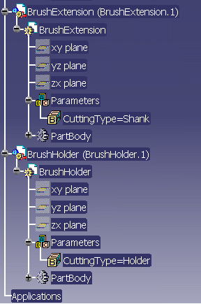
Parts of this CATProduct are the components of the tool:
The tool created from the CATProduct can be used in Video simulation. This tool can have multiple cutters, holders, and shanks.
Please note however that user representation may reduce the performance of the material removal simulation.
To allow Parameter nodes to be displayed in the PPR tree, make the following settings in Tools > Options:
You can define tool geometry as a CATProduct file. CATParts instantiated in this CATProduct (there may be intermediate products between root product and parts at any level ) are components of this tool. A given component may be instantiated several times in the product, at different locations.
Some components are cutting components and are used in simulation and in In-Process Model (IPM) generation. Some other components are non-cutting and are used in collision detection. A non-cutting component may be a shank or a holder. These sub-categories of non-cutting components must be differentiated as well.
To identify the type of a component, the corresponding CATPart must contain
a Knowledgeware parameter (added using the Fx button in Part Design).
Parameter name is CuttingType (type string).
Possible values of this parameter are CUTTER, SHANK and
HOLDER.
Any CATPart not containing this parameter is ignored in the simulation and in
IPM generation.
Note that Photo simulation allows one shank or holder only.
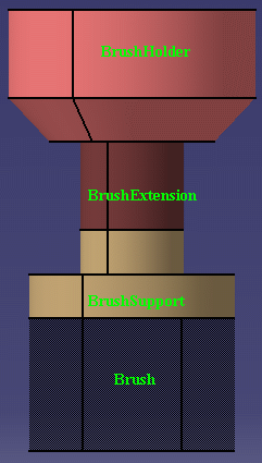
In the following example:
You can perform material removal with tool assemblies with multiple cutting parts.
For example:
If you perform machining with the tool assembly as shown above, then all three cutting parts should be considered for material removal.
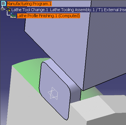
You can attach a CATProduct to a lathe tool by means of the NC Resources > Add User Representation contextual command in the Resource List.
Parts of this CATProduct are the components of the lathe tool:
The lathe tool user representation can be used in Video simulation. However, unlike the user representation used for milling tools, only one cutting and one non-cutting component can be used for lathe tools. Also, the insert holder does not participate in material removal (regardless of Rapid or Feed mode) and is used only for collision detection.
The sketch conventions outlined below for cutting and non-cutting components must be respected. Non-cutting parts must be convex (that is, the profiles used do not have any cut-outs).
Please note however that user representation may reduce the performance of the material removal simulation.
To allow Parameter nodes to be displayed in the PPR tree, make the following settings:
To allow you to pick individual points during the material removal simulation, make the following setting:
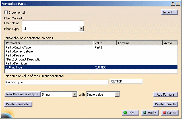
Create a part (New > Part) then select the F(x) Formula command.
In the Formula dialog box, set CuttingType to CUTTER.
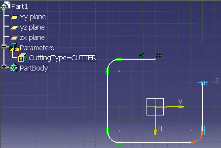
In the Sketcher workbench, select the ZX plane (in lathe machining, Z is the spindle axis and X is the radial axis). Create a closed profile, adding successive elements in the anti-clockwise direction.
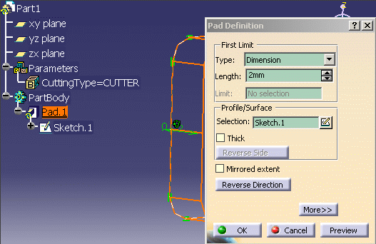
In the Part Design workbench, create a Pad from the sketch (2mm thick, for example). This will represent the lathe insert.
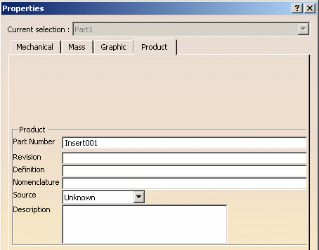
Right-click the Part in the tree and select Properties. Rename the Part Number (Insert001, for example).
Save the CATPart.
Define the non-cutting component using the same procedure.
Create a part (New > Part) then select the F(x) Formula command. In the Formula dialog box, set CuttingType to HOLDER.
In the Sketcher workbench, select the ZX plane. Create a rectangle.
In the Part Design workbench, create a Pad from the sketch. This will represent the lathe insert holder.
Right-click the Part in the tree and select Properties. Rename the Part Number (Holder001, for example).
Save the CATPart.
Create a new CATProduct instantiated with the Insert and Holder CATParts.
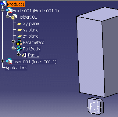
You can then use the CATProduct as the Tool in the Video simulation.
A Cleaning operation is a non-machining operation that uses a CATProduct user representation tool. It is defined by first creating a machining operation (depending upon the strategy required by the cleaning process) so as to generate the tool path for cleaning. Then by assigning a specific user representation tool a cleaning behavior can be simulated. Cleaning simulation can be performed in Video mode only.
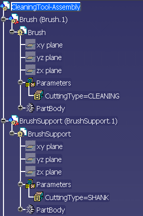
The tool assigned to cleaning operations must be a CATProduct user representation and must conform to the following rules. The CuttingType knowledge attribute needs to be defined with a value equal to CLEANING for defining the cleaning component of the tool (which may be a brush, for example). Possible values for the non-cleaning components are SHANK and HOLDER.
In operations where cleaning tools as described above are used, the Video simulation has the behavior as illustrated below:
Note that Cleaning tools are not supported for turning operations or in Photo mode.
Please note that the CATProduct user representation of tools described above is the recommended method.
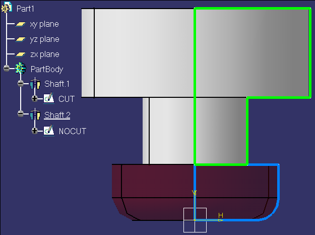
You can attach a CATPart to a tool or tool assembly by means of the NC Resources > Add User Representation contextual command in the Resource List.
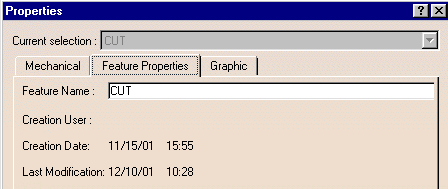
You can add a sketch called CUT to define the
cutting part of the tool and, optionally, a sketch called NOCUT to define the
non-cutting part of the tool. These profiles will be used in the material
removal simulation in Photo or Video mode.
Note that the sketches must be called CUT and NOCUT: no other names are
possible.
Please note however that user representation may reduce the performance of the material removal simulation .
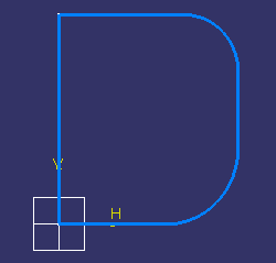
Here is a step-by step procedure for defining the CUT and NOCUT profiles.
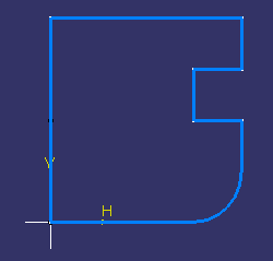
Define a closed profile representing the cutting part of the tool:
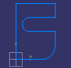
Examples of correct profiles:
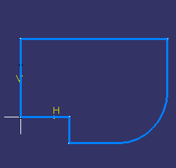
If needed, define a profile representing the non-cutting part of the tool:
The following can be defined as stock, design or fixtures in the Part Operation editor:
Video results can be used effectively in a Part Operation that contains more that one program. The Video result of the last operation of a program can be used as the stock for a following program. For that, you must set the Simulation at Part Operation level option and use the Video from Last Saved Result command when using simulation in the following program.
If there is no stock defined, the envelope volume of the design part is used. If there is no design part, the envelope volume of the design part is used.
In Video mode only, if the stock geometry is not correctly closed, a stock representing the envelope volume of the design part is computed.