|
|
This task shows you how to specify tool compensation information. | |
|
|
1. | In the Tool Definition dialog box click More to expand the dialog box and access all the tool's parameters, then select the Compensation tab. |
| 2. | Right-click the desired compensation site to either edit
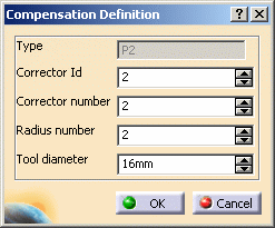
or add tool compensation data. The Compensation Definition dialog box is displayed allowing you to specify the tool's compensation characteristics. |
|
| 3. | You can associate the following information
to each compensation site on a tool:
Some tool types (such as Face mills) have only one compensation site. This is the site P1 located at the extremity of the tool. Other tool types (such as Drills) have more than one compensation site. Some sites are defined by means of a diameter value. Refer to Tools for Milling and Drilling Operations for more information. |
|
| 4. | Click OK to update the tool with the desired compensation information. | |
|
|
It is possible to define tool compensation site numbers for all machining operation types, if tool compensation numbers are already defined on the tool used by the machining operation. In general, the tool compensation site number used by
the operation can be specified. For turning operations, tools (that is, insert holder and insert) have nine compensation sites P1 to P9. Their position depends on the type of insert used. Please refer to the Lathe Machining User's Guide for more information about cutter compensation. |
|
|
|
||
