Creating a 3D profile on the view support plane |
|
-
Make sure the section view is active. If not, double-click to activate it.
-
Click 3D Profile
 in the 3D Geometry toolbar.
-
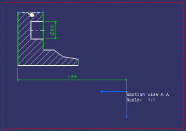
Select the line as shown below.

The Profile Definition dialog box appears, displaying the name of the 3D profile you are creating in the Name field. The geometry you selected is displayed in the Input Geometry list. The resulting geometry (that is all geometrical elements that eventually make up the 3D profile) is displayed in the Output Geometry list.

You can select an element from these lists if you want it to be highlighted in the 2D and 3D windows. 
-
Enter a name for your 3D profile, Shaft for example.
-
Optionally choose a color for your 3D profile (the color is not applied to the geometry referenced by the profile).
-
Choose a mode from the associated drop-down list.
-
Point (Explicit Definition): you need to select all the points of interest. In that case, the Input Geometry and Output Geometry fields show the same elements.
-
Wire (Automatic Propagation): after you select a geometrical element, the application detects and selects all connex elements. In that case, the Input Geometry and Output Geometry fields do not show the same elements.

In certain specific geometrical configurations, an ambiguity may arise, in which case some elements in the profile remain unselected. You can solve the ambiguity by selecting the remaining elements to include in the profile. -
Wire (Explicit Definition): you need to select all the geometrical elements of interest. In that case, the Input Geometry and the Output Geometry fields show the same elements.
For the purpose of this scenario, make sure the Wire (Automatic Propagation) option is selected from the list.
-
-
Optionally choose one or several checks to perform. This is to verify that the profile is usable for solid or surface definition.
-
Check tangency
-
Check connexity
-
Check manifold
-
Check curvature
Once checks are performed, warning messages may appear to help you decide whether you can keep your definition as such or if you need to modify it. Note that you can validate the profile definition even if there are some warnings. However, when updating the 3D, you may get an update error (depending on the kind of warning).
-
-
Click OK to validate and close the dialog box. The 3D profile is created, on the same plane as the section view, and it is listed in the specification tree, under the PartBody node.


- Of all elements created from 2D geometry in 2D Layout for 3D Design, only 3D profiles and 3D planes belong to the current part body.
- Note that 3D profiles and 3D planes are created under the current part body only when working in a hybrid design environment, that is when the Enable hybrid design inside part bodies and bodies option is selected in Tools > Options > Infrastructure > Part Infrastructure > Part Document tab (which is the case by default). Otherwise, when this option is not selected, 3D profiles and 3D planes are created in geometrical sets or ordered geometrical sets.
Creating a 3D profile on a plane parallel to the view support plane |
|
-
Double-click the front view to activate it.
-
Click 3D Profile
 in the 3D Geometry toolbar.
 -
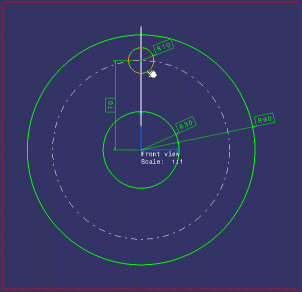
Select the R10 circle as shown below.

The Profile Definition dialog box is displayed. -
Choose a support plane. You can either:
-
select an existing plane, such as the xy, yz or zx plane, the face of a pad, or an existing 3D plane (for more information, refer to Creating a 3D Plane).
-
define a parallel plane on the fly by selecting a line in another layout view (provided the support plane in this view is orthogonal to the support plane you are defining).
For the purpose of our scenario, you will define a plane on the fly. To do this, right-click inside the Support Plane field.
-
-
Select Create Plane in the contextual menu which is displayed.
-
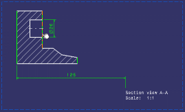
Select the line in the section view as shown below.

The 3D plane, Plane2DL.1, is created and it is listed in the specification tree, under the PartBody node.

- You can only create a plane parallel to the support plane of the current view. An error message is displayed when selecting a line that would lead to the creation of a non-parallel plane.
- The 3D plane is associative to the selected line: if the line is modified, the support plane will be recomputed when updating the plane (by exiting the 2D Layout for 3D Design workbench or using the Update 3D Profile command) to reflect the modifications.
-
In the Profile Definition dialog box, enter a name for your 3D profile (Pocket for example).
-
Make sure Plane2DL.1 is selected in the Support Plane field.
-
Click OK to validate and close the dialog box.
The 3D profile is created, by projecting the circle on the support plane which is parallel to the front view. It is listed in the specification tree under the PartBody node.
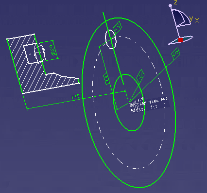
Furthermore, the 3D plane and profile are displayed in the 3D window.

More about creating 3D profiles
You can create as many 3D profiles as needed from a design view. 3D profiles can be created on the support plane of the view, as well as on any plane parallel to the view support plane. You can use an existing plane, or define a parallel plane on the fly during the 3D profile creation.
You cannot create 3D profiles for geometry contained in isometric views (because they are not design views).
3D profiles:
- can be created for any 2D geometry contained in a design view, in a part layout (a CATPart document).
- can contain 2D geometry which is already included in other 3D profile or plane (in other words, any 2D geometry can be included in several 3D outputs).
- can be updated independently of the layout. During an update operation, a given 3D profile is only impacted when the 2D geometry is modified.
- have their own graphic properties, independent from the graphic properties of the 2D geometry which makes up the profile.
- let you expose in a part a set of connected curves or a set of points.
- can be used to create Part Design or Generative Shape Design features.
- can be created within a Part Body, regardless of hybrid design setting. On this point, 3D profiles are similar to sketcher output profiles.
- You can edit a 3D profile by right-clicking it from the specification tree and selecting Profile definition. This command is only accessible in the Part Design and Generative Shape Design workbenches.
- Deleting a 3D profile does not delete the original 2D geometry in the layout. A 3D profile can only be deleted from the Part Design and Generative Shape Design workbenches.
- Deleting the 2D geometry used as input when defining a 3D profile in a view (which can only be done from the 2D Layout for 3D Design workbench) prevents the 3D profile from being re-built.
- It is not possible to paste a non-isolated profile/plane in the As specified in Part document format, but only in the As Result format.
- Powercopy is not available for 3D profiles.
![]()