-
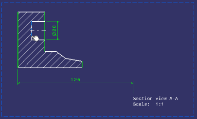
Double-click the front view to activate it.
-
Click 3D Plane
 in the 3D Geometry toolbar (3D Outputs
sub-toolbar).


-
Select the line in the section view as shown below.

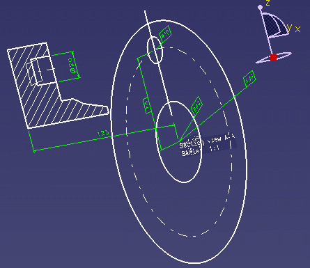
The 3D plane, Plane2DL.1, is created and it is listed in the specification tree, under the PartBody node.


- Of all elements created from 2D geometry in 2D Layout for 3D Design, only 3D profiles and 3D planes belong to the current part body.
- Note that 3D profiles and 3D planes are created under the current part body only when working in a hybrid design environment, that is when the Enable hybrid design inside part bodies and bodies option is selected in Tools > Options > Infrastructure > Part Infrastructure > Part Document tab (which is the case by default). Otherwise, when this option is not selected, 3D profiles and 3D planes are created in geometrical sets or ordered geometrical sets.
The 3D plane is also displayed in the 3D window.

More about creating and using 3D planes
You can create as many 3D planes as needed from a design view. 3D planes can be created:
- from any line contained in a design view, in a part layout (a CATPart document).
- from a line which is already included in other 3D planes or profiles (in other words, any 2D geometry can be included in several 3D outputs).
You cannot create 3D planes in isometric views (because they are not design views).
3D planes can be used to create:
- Part Design or Generative Shape Design features.
- 3D profiles on a plane parallel to the view support plane. For more information, refer to Creating a 3D Profile.
- Deleting a 3D plane does not delete the original 2D geometry in the layout. A 3D plane can only be deleted from the Part Design and Generative Shape Design workbenches.
- Deleting the 2D geometry used as input when defining a 3D plane in a view (which can only be done from the 2D Layout for 3D Design workbench) prevents the 3D plane from being re-built.
- It is not possible to paste a non-isolated profile/plane in the As specified in Part document format, but only in the As Result format.
- Powercopy is not available for 3D planes.
- You can only create a plane parallel to the support plane of the current view. An error message is displayed when selecting a line that would lead to the creation of a non-parallel plane.
- The 3D plane is associative to the line you select when creating it: if the line is modified, the support plane will be recomputed when updating the plane (by exiting the 2D Layout for 3D Design workbench or using the Update 3D Profile command) to reflect the modifications.
![]()