-
Select Start > Mechanical Design from the menu bar.
-
Select the 2D Layout for 3D Design workbench.
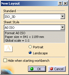
The New Layout dialog box is displayed, allowing you to choose a standard, a sheet style and an orientation for your new layout. Among other things, the sheet style defines the sheet format, paper size, scale and default orientation.

-
Select the JIS_3D standard.

Standards and sheet styles are defined by the administrator in the Standards Editor, who can add an unlimited number of them. Note that any customized standard is based on one of the four international standards (ANSI, ISO, ASME or JIS) as far as basic parameters are concerned. For more details, see Sheet Format Definition and Sheet styles in the Administration Tasks chapter. 
In the New Layout dialog box, standards suffixed with _3D are specifically designed for 2D Layout for 3D Design layouts. For example, colors have been customized for optimized display. For more information, refer to Layout Views Customization in the Administration Tasks chapter. -
Select the A4 JIS sheet style.
-
Optionally change the default orientation from Landscape to Portrait.
-
If you do not want the New Layout dialog box to appear the next time you enter the 2D Layout for 3D Design workbench via the Start menu, select the Hide when starting workbench option.

In this case, the last selected standard, sheet style and orientation will be used by default when creating a layout. You will always be able to reactivate this dialog box by unselecting the Hide when starting workbench option available through Tools > Options > Mechanical Design > Drafting > General tab. -
Click OK.
The New Part dialog box is displayed. -
Enter a name for the part that will be associated to your layout (Disk, for example) and click OK.
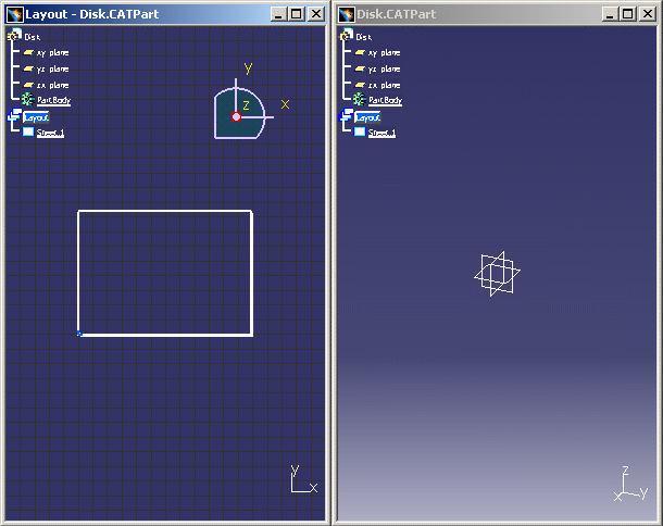
An empty sheet is created in a specific 2D window, and the associated part document is created and opened in a 3D window.


- The sheet appears in the specification tree (under the Disk.CATPart item) both in the 2D and 3D windows. Pressing the F3 key lets you show or hide the specification tree as desired.
- The creation of a layout cannot be undone.
- Local transformations are planar, which means that the sheet cannot be rotated in 3D.
- By default, the background is blue and not graduated in the 2D window, which enables you to differentiate it from the 3D window which is blue and graduated.
- Refer to Navigating Between Windows to learn how to switch back and forth between the 2D and 3D windows.
About standards
- At any time after defining a sheet, you can change the standard (which you can update), sheet style or orientation. Refer to Modifying a Sheet for more information.
- Only one standard can be associated to a given part, which
guarantees standard homogeneity within the part. This may have
consequences in the case of a part containing a mix of layout
elements and 3D annotations (Functional Tolerancing and Annotation
elements):
- The standard selected when creating a layout also becomes the
standard used for 3D annotations. If 3D annotations previously
used a different standard, this implies that:
- the visualization of some of these annotations may change.
- you cannot use an older standard for the layout (for example, you cannot use a standard created in R15 for the layout if 3D annotations used a standard created in R16).
- Likewise, when creating a 3D annotation for the first time in a part which already contains a layout, the standard used for 3D annotations also becomes the standard used for the layout. This implies that if the layout previously used a different standard, the visualization of some layout elements may change.
- Changing the standard of a layout also changes the standard used for 3D annotations, and vice-versa.
To prevent confusion, administrators are free to provide one standard only to their users.
As a reminder, the standard used for a part is defined by the Default standard at creation option available in Tools > Options > Infrastructure > 3D Annotations Infrastructure > Tolerancing tab.
- The standard selected when creating a layout also becomes the
standard used for 3D annotations. If 3D annotations previously
used a different standard, this implies that:
Rendering Mode
![]()
