Defining Layout Views
Defining layout views is an important step in the layout design process. Designers need to have a general idea of the overall dimensions of their design, as well as of its position in space.
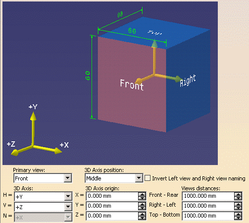
When customizing layout views, administrators actually define the 2D Layout for 3D Design view box, which gathers all the data needed to fully define the layout of a view set in the 2D window, as well as the position of each view in the 3D space.
This data is made up of:
-
Primary view type
-
3D axis
-
View box anchor point
-
3D axis origin
-
View box overall dimensions
A single, default, view box is defined for each standard (for example, there is a single view box for the ISO_3D standard). The standard definition is retrieved when creating the first view of a view set: the view box definition is associated to each view set. Therefore, an update of the standard does not impact existing views.
Administrators will probably want to customize layout views for the ASME_3D, ISO_3D and JIS_3D standards, which have been specifically customized for the 2D Layout for 3D Design workbench (the colors, for example, have been customized for optimized display).
On the other hand, it does not make much sense to customize layout views for the ISO, JIS, ANSI and ASME standards, which are purely 2D-based, Drafting standards.
The view box is defined in the Layout Views Customization node of the Standard Definition editor, available via Tools > Standards.
-
Click on the Layout Views Customization node of the Standard Definition editor. The editor is displayed.

-
Define the primary view type (Front, Right, Rear, Left, Top or Bottom) from the Primary view drop-down list.
-
Define the view box anchor point from the 3D Axis position drop-down list.
-
Select Invert Left view and Right view naming if you want the Right view to be called Left view, and vice-versa. This only inverts the name (not the type) of the views.
-
Define the 3D axis from the 3D Axis: H (horizontal), V (vertical) and N (normal) drop-down lists: this specifies which plane the primary view lies on and which orientation has the outgoing normal.
For example, defining a front view on the xy plane and +z normal means that the rear view is located below the front view, along the z axis. On the opposite, defining a front view on the xy plane and -z normal means that the rear view is above the front view, along the z axis. -
Define the 3D axis origin from the 3D Axis origin: X, Y and Z drop-down lists.
-
Define the view box overall dimensions from the Views distances: Front-Rear (distance from the front to the rear of the box), Right-Left (distance from the right hand-side to the left hand-side of the box) and Top-Bottom (distance from the top to the bottom of the box) drop-down lists.