Tile the 2D and 3D windows vertically as you now need to have both windows displayed.
In the 3D window, you can see that elements are pre-positioned, but no 3D element is created. If you right-click the views in the 2D window and then select Visualization > Hide in 3D, you will see that the geometry is hidden, and that no part exists. To display the geometry again, right-click the views again and select Visualization > Show in 3D.
Creating a 3D profile |
|
|
|
At this stage, you will create a 3D profile to use as a reference element when creating the shaft. |
-
In the 2D window, make sure the section view is still active from the previous task. If not, double-click to activate it.
-
Click 3D Profile
 in the 3D Geometry toolbar.
 -
Select the line as shown below.
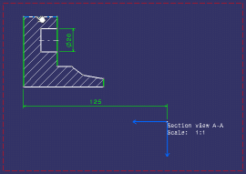
The Profile Definition dialog box is displayed.
-
Enter a name for your 3D profile, Shaft for example.
-
Make sure the Wire (Automatic Propagation) option is selected from the Mode: drop-down list.
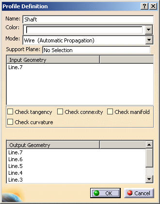
-
Click OK to validate and close the dialog box. The 3D profile is created, on the same plane as the section view, and it is listed in the specification tree, under the PartBody node.


Of all elements created from 2D geometry in 2D Layout for 3D Design, only 3D profiles and planes belong to the current part body.
Creating a 3D profile on a support plane parallel to the 3D view plane |
|
|
|
At this stage, you will create a 3D profile on a plane which is parallel to the 3D view plane. This parallel plane will be used as a support plane when creating the pocket. |
-
Double-click the front view to activate it.
-
Click 3D Profile
 in the 3D Geometry toolbar.
 -
Select the R10 circle as shown below.
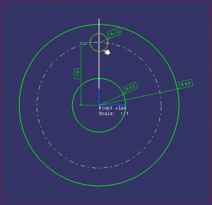
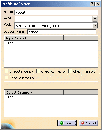
The Profile Definition dialog box is displayed. -
Right-click inside the Support Plane field.
-
Select the Create Plane option in the contextual menu which is displayed.
-
Select the line as shown below.
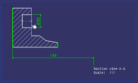
The 3D plane, Plane2DL.2, is created and listed in the specification tree, under the PartBody node.
-
Back in the Profile Definition dialog box, enter a name for your 3D profile, Pocket for example.
-
Make sure Plane2DL.1 is selected in the Support Plane field.
-
Click OK to validate and close the dialog box.
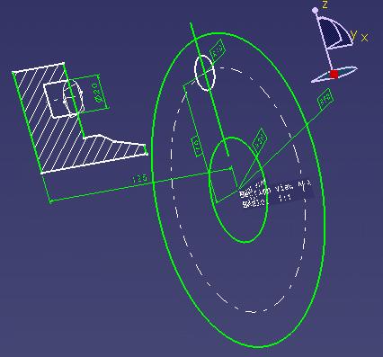
The 3D profile of the circle is created on the support plane which is parallel to the front view. It is listed in the specification tree under the PartBody node.
Furthermore, the 3D plane and 3D profile are displayed in the 3D window.
Creating a 3D plane |
|
|
|
At this stage, you will create a 3D plane to use as a limit when defining the pocket depth. |
-
Make sure the front view is still active from the previous task. If not, double-click to activate it.
-
Click 3D Plane
 in the 3D Geometry toolbar.
 -
Select the line as shown below.
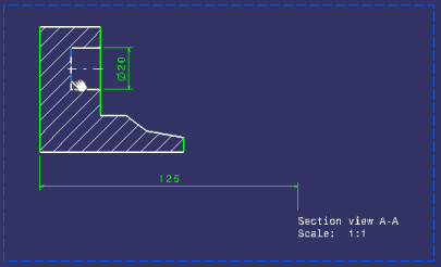
- The Profile Definition dialog box is displayed. Click OK.
-
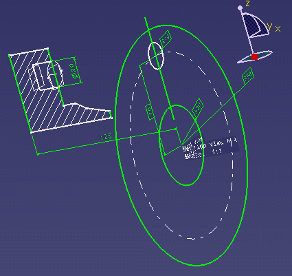
The 3D plane is created, on the same plane as the previous one. It is displayed in the specification tree as the Plane2DL.2 feature, as well as in the 3D window.
Creating a shaft |
|
-
Optionally, right-click the views in the 2D window and select Visualization > Hide in 3D from the contextual menu to hide the 2D geometry from the 3D window. Only the elements that will be used to create the solid are visualized.
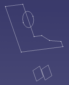

To display the geometry again, right-click the views again and select Visualization > Show in 3D from the contextual menu. -
Activate the 3D window.
-
Click Shaft
 .
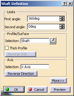
The Shaft Definition dialog box is displayed.
 -
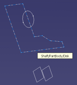
Select the Shaft feature as the profile, either from the 3D geometry area or from the specification tree.
-
In the Axis area, right-click the Selection field.
-
Select X Axis as the axis for the shaft in the contextual menu which is displayed. A preview of the shaft is displayed.
-
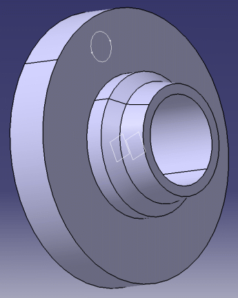
Click OK to validate and close the dialog box. The shaft is created.
Creating a pocket |
|
-
Still in the 3D window, select the Pocket feature as the profile, either from the 3D geometry area or from the specification tree.
-
Click Pocket
 .
The Pocket Definition dialog box is displayed.
 -
Select Up to plane as the type.
-
From the specification tree, select Plane2DL.2 as the limit for the pocket.
-
Click OK to validate and close the dialog box. The pocket is created.
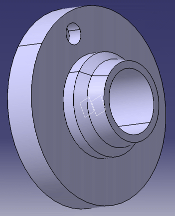
Creating a circular pattern |
|
-
Still in the 3D window, select Pocket.1 from the specification tree.
-
Click Circular Pattern
 in the Transformation toolbar (Pattern
sub-toolbar). The Circular Pattern Definition dialog box is
displayed.
 -
Select Complete Crown from the Parameters drop-down list.
-
Enter 4 in the Instance(s) field.
-
As the reference element, right-click the field and select X axis from the contextual menu.
-
Select the pocket (Pocket.1) as the object to pattern.
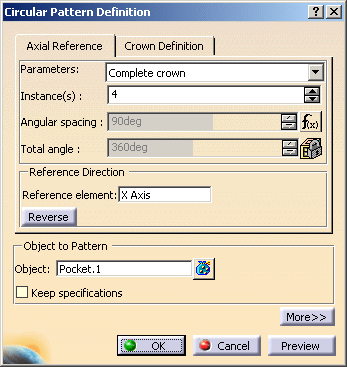
-
Click OK to validate and close the dialog box. The circular pattern is created.
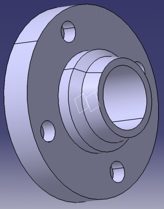
Checking your layout |
|
|
|
Now that you have created your 3D part, you can check your layout to make sure it is correct. |
-
Activate the Layout window.
-
Right-click the front view and select Background >
 Standard.
 -
Repeat this operation for the section view. The 3D background of your layout is displayed in the 2D window.
-
In the Visualization toolbar, activate the Cutting Plane
 icon. The 3D background of the Section view is cut along its definition
plane.
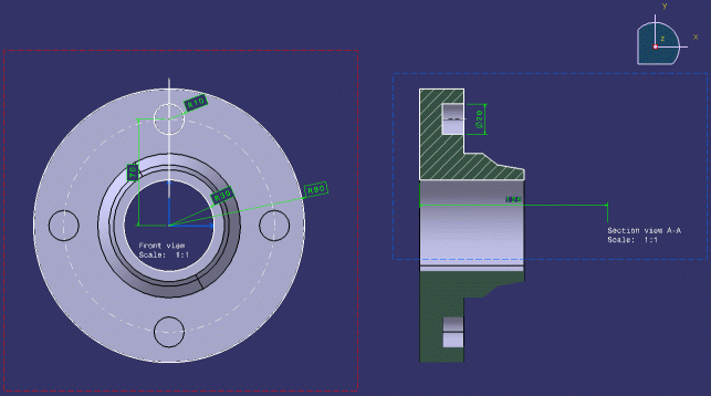
For more in-depth information about the various functionalities available in 2D Layout for 3D Design, refer to the User Tasks chapter.
![]()