Creating a section view |
|
-
Click Line
 in the Geometry Creation toolbar.
 -
Use the vertical axis to define the cutting profile as shown below, and double-click to end the line creation.
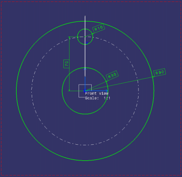
-
Click New Section/Auxiliary View
 in the Layout toolbar (Views sub-toolbar).

-
Select the line you have just created as the cutting profile.
-
In the Tools Palette which is automatically displayed, select the Section View icon
 .
.

This option is also available from the contextual menu. -
Click in the layout at the location where you want the section view to be positioned.

Positioning the view also defines the section view direction, as if it were a left or a right projection view. A section view is created. Additionally, the Section view item is added to the specification tree. Note that the 2D background is shown in the section view, enabling you to see the cutting profile from the front view.
Hiding the 2D and 3D backgrounds |
|
|
|
At this stage, you will hide both the 2D background (i.e. the 3D representation of 2D elements which do not belong to the current view, but to other views) and the 3D background (i.e. the representation of all 3D elements, including edges, faces and 3D wireframe) from the front and section views. |
-
Right-click the front view and select Background >
 Invisible.
 -
Repeat this operation for the section view. The 2D background is now hidden from the section view (you do not see the cutting profile anymore).

You can also multi-select the views and then perform this operation.
Defining the view content using folding lines |
|
|
|
At this stage, you will see how to add geometry in the view using folding lines as a guide. You can use folding lines for any kind of view, as long as the planes they correspond to are not parallel. For example, you cannot have folding lines between a front view and a rear view. |
-
Double-click the section view to activate it.
-
Right-click the front view to display the contextual menu.
-
Select Front view object > Show Folding Lines. The folding lines are displayed.
-
Click the Profile icon
 in the Geometry Creation toolbar.
 -
In the section view, define the profile as shown below, using the folding lines as a guide, and double-click when done.
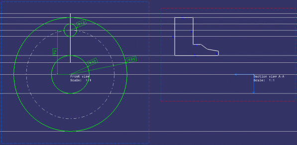
-
Repeat steps 4 and 5 to define another profile for the hole.
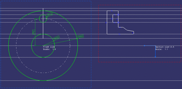
-
Right-click the front view to display the contextual menu.
-
Select Front view object > Hide Folding Lines. The folding lines are hidden.
Fixing the geometry together |
|
-
Click Fix Together
 in the Constraint toolbar.
 -
Using the Ctrl key, multi-select the profile you have created in step 4 of the previous task (i.e. the external profile, not the hole profile). The Fix Together Definition dialog box is displayed.
-
Click OK. The geometry in the section view is now rigidly constrained.
Adding dress-up |
|
|
|
At this stage, you will add dress-up elements to the section view. This will make your layout clearer. |
|
|
You may now want to hide constraints. To do this, in the
Visualization toolbar, deactivate the Show Constraints
|
-
Click Axis Line
 in the Dress-up toolbar (Axis and Threads
sub-toolbar).
 -
Select the first and then the second line of reference as shown below.
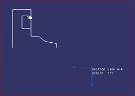
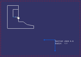
The axis line is created.
-
Click Area Fill
 in the Dress-up toolbar. The Area detection dialog
box is displayed.
 -
Leave the default option (Automatic) selected, and click inside the section view profile area.
The area fill is created.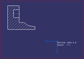
Creating dimensions |
|
|
|
The dimensions that you will be creating in this task will be driving dimensions, as defined in the previous task when configuring your options. |
-
Click Dimensions
 in the Dimensioning toolbar. The Tools Palette is
automatically displayed.
 -
Select the section view vertical axis, and then the line as shown below.
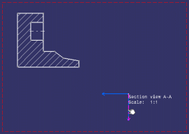
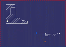
A preview of the dimension to be created is displayed.
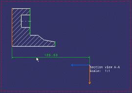
-
If the previewed value is not 125, type 125 in the Value field of the Tools Palette and then press enter. The whole geometry is moved accordingly.
-
Click at the location where you want to position the dimension. The dimension is created.
-
Click Diameter Dimensions
 in the Dimensioning toolbar (Dimensions
sub-toolbar).
 -
Select the first and then the second line defining the hole.
-
Click at the location where you want to position the dimension. The dimension is created, with a value of 20 (if you properly defined the hole profile using the folding lines).
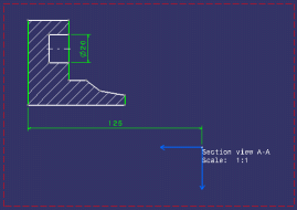
-
If you wish, you can continue creating dimensions until the geometry in the section view is fully iso-constrained. The whole geometry should be green, as defined for iso-constrained elements in the Diagnostic colors dialog box. This setting is available via Tools > Options > Mechanical Design > Drafting > Geometry tab, Colors button next to the Visualization of Diagnostic option.
-
Re-position your dimensions if necessary.
Creating a formula |
|
|
|
At this stage, you will be creating a formula specifying that the diameter dimension value (in the section view) is equal to the radius dimension value of the hole (in the front view) multiplied by 2. The radius dimension value will then drive the diameter dimension value. |
-
Click Formula
 in the Knowledge toolbar.
The Formulas: Layout dialog box is displayed. -
Select the diameter dimension you created in steps 6 and 7 of the previous task. The parameters list is updated with the parameters associated to this dimension.
-
Make sure the parameter (Offset) that specifies the dimension value is selected.
-
Click the Add Formula button. The Formula Editor dialog box is displayed.
-
Select the R10 dimension in the front view to add it to the formula field.
-
Still in the formula field, type *2.
-
Click OK to close the Formula Editor dialog box. The formula you have just created is listed in front of the associated parameter in the Formulas: Disk dialog box.
-
Click OK to validate and close the Formulas: Disk dialog box.
If you now edit the radius dimension value from 10 to 11, for example, you will notice that the diameter dimension value changes to 22.
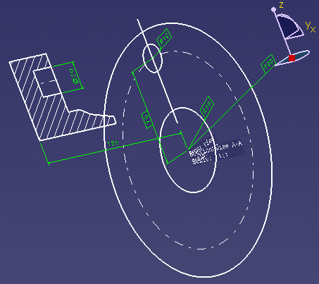 |
You can now create the 3D part from this preliminary design.
![]()