Tooling for Profile Finish Turning
The following tooling may be used:
- External and Internal insert-holders with all insert types except groove and thread.
- External and Internal Groove insert-holders with groove and trigon
inserts.
Refer to Trigon Insert Used on a Groove Insert-holder for more information about this tooling configuration.
Note that the following attributes may influence machining (they are located on the Insert-holder's Technology tab):
- Gouging angle
- Trailing angle
- Leading angle
- Max Recessing Depth
- Max Cutting Depth
- Max Boring Depth.
These attributes take tooling accessibility into account and may reduce
the machined area.
However, you can use the Insert-Holder Constraints option on the
operation editor to either ignore or apply these tooling attributes. You
can replay the operation to verify the influence of these attributes on the
generated tool path.
Note that the Insert-Holder Constraints setting does not influence the Leading and Trailing Safety Angles defined in the operation editor.
Geometry for Profile Finish Turning
A Part profile is required. It can be specified as follows:
- select edges either directly or after selecting the By Curve contextual command. In this case the Edge Selection toolbar appears to help you specify the guiding contour.
- select the Sectioning contextual command. Please refer to
Sectioning for details of how to use this capability.
Please note that the sectioning selection method is not associative.
Start Limit: None / In / On / Out
This option allows you to specify a point, line,
curve or face as the start element of the part
profile. If a face is specified, the start element is
the intersection of the face and the working plane.
The position of the start of machining is also
defined with respect to this element.
In / On / Out: allows you to specify the Go-Go type positioning of the tool with respect to the start element. Go-Go type positioning of tool in general positions the tool based on its radius and tool compensation number. This means positioning will vary for different tool insert geometries with respect to the limit and there is possibility of tool going beyond limit even with IN option. The On option is always used for a point type start element. If needed, the profile may be extrapolated to the start element.
End Limit: None / In / On / Out
This option allows you to specify a point, line, curve or face as the end
element of the part profile. If a face is specified, the end element is the
intersection of the face and the working plane. The position of the end of
machining is also defined with respect to this element.
In / On / Out: allows you to specify the Go-Go type positioning of the tool with respect to the end element. Go-Go type positioning of tool in general positions the tool based on its radius and tool compensation number. This means positioning will vary for different tool insert geometries with respect to the limit and there is possibility of tool going beyond limit even with IN option. The On option is always used for a point type end element.
Note: To avoid collisions of tool with Limit geometry or unwanted machining beyond limits with IN option, either define limits with suitable offset value or include Limit geometry as part element (this is better wherever applicable) and avoid limit definition.
Relimiting the area to machine by means of limit elements
If you specify a point, it is projected onto the part profile.
A line through the projected point parallel to the radial axis delimits the
area to machine.
If you specify a line, its intersection with the part profile is calculated
(if necessary, the line is extrapolated).
A line through the intersection point parallel to the radial axis delimits
the area to machine.
If you specify a curve, its intersection with the part profile is
calculated (if necessary, the curve is extrapolated using the tangent at
the curve extremity).
A line through the intersection point parallel to the radial axis delimits
the area to machine.
If needed, the profile may be extrapolated to the end element.
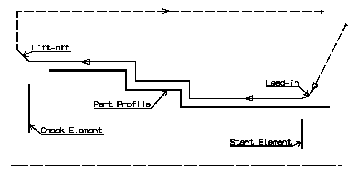
The figure above illustrates the use of start and end elements for Profile Finish Turning. Profile is machined from start element. Profile is extrapolated up to end element. Direct approach and radial-axial retract.
Orientation and Location for Profile Finish Turning
- Orientation: Internal / External / Frontal
This option allows you to specify the type of machining according to the location of the area to machine on the part.
- Location:
- Front, the profile is machined toward the head stock
- Back, the profile is machined from the head stock.
Corner Processing for Profile Finish Turning
The following options allow you to define how corners of the profile are to be machined:
- None: no corners are to be machined along the profile
- Chamfer: only 90 degree corners of the profile are chamfered
- Rounded: all corners of the profile are rounded.
Corner processing options are also available to define how the entry and exit corners are to be machined. Entry and exit corners are defined by either a chamfer length, or a corner radius and corner angle.
Part Offsets for Profile Finish Turning
- Part offset, which is defined perpendicular to the part profile.
- Axial part offset.
- Radial part offset.
- Start limit offset: distance with respect to the start element (only if start element is a line or a curve, and when In or Out is set for start element positioning).
- End limit offset: distance with respect to the end element (only if end element is a line or a curve, and when In or Out is set for end element positioning).
Offsets can be positive or negative with any absolute value. The global offset applied to the part profile is the resulting value of the normal, axial and radial offsets.
In addition to these global values, local offsets can be applied to segments, curves and arcs of the part profile.
Machining Strategy Parameters for Profile Finish Turning
Path Definition for Profile Finish Turning
- Machining Direction: To or From Spindle
This option is only available for frontal machining for specifying the machining direction with respect to the spindle axis.
If start and end elements are defined that are in conflict with the machining direction, then these elements will be reversed automatically.
- Contouring for Outside Corners: Angular / Circular
Allows you to define whether contouring of corners is to be angular or circular. Note that the part profile is respected in this case.
- Under Spindle Axis Machining
When finishing in frontal mode, this option allows you to request machining under the spindle axis. - Recess Machining
When this option is set, a recess machining path is done after the profile finish path.
The trailing safety angle option becomes available.
- Leading and Trailing Safety
Angles
The insert geometry is taken into account to avoid collision by reducing the maximum slope on which the tool can machine. The Leading Safety Angle and Trailing Safety Angle allow you to further reduce this slope.
Leading and trailing angles can also be defined on the insert-holder to define the maximum slope on which machining can be done. In this case and if the Insert-Holder Constraints setting is applied (see above), the angles that reduce the slope the most will be taken into account. - Machining Tolerance for following the profile.
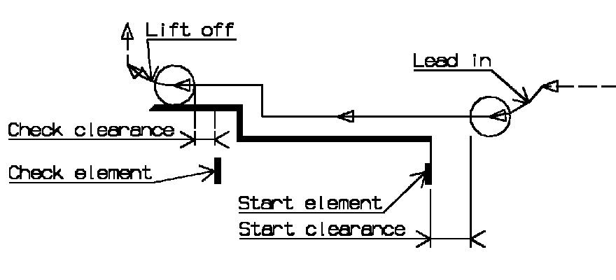
Lead-in and Lift-off for Profile Finish Turning
- Lead-in type: Linear / Circular
Defines the type of lead-in onto the profile at lead-in feedrate- Linear: lead-in up to the point where profile machining starts is defined by means of the lead-in distance and lead-in angle parameters.
- Circular: lead-in is circular and tangent to the point where profile machining starts. It is defined by means of the lead-in radius and lead-in angle parameters.
Note that the lead-in angle is defined with respect to the normal to the cutting direction. Range of lead-in angle is from -90 to 135 degrees for all tool types except for a grooving tool, where it ranges from 0 to 90 degrees.
The figure below shows an example of linear lead-in and circular lift-off (external machining is assumed).
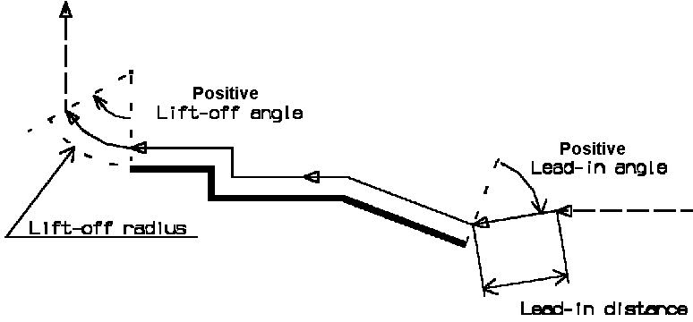
- Lift-off type: Linear / Circular.
Defines the type of lift-off from the profile at lift-off feedrate- Linear: lift-off from the point where profile machining ends is defined by means of the lift-off distance and lift-off angle parameters.
- Circular: lift-off is circular and tangent from the point where profile machining ends. It is defined by means of the lift-off radius and lift-off angle parameters.
Note that the lift-off angle is defined with respect to the normal to the cutting direction. Range of lift-off angle is from -90 to 135 degrees for all tool types except for a grooving tool, where it ranges from 0 to 90 degrees.
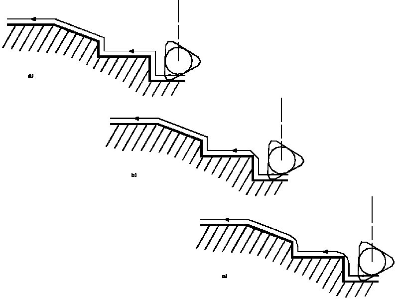
In the example below, the round tool is tangent In start element plus clearance at start of profiling. Round tool is tangent Out end element plus clearance at end of profiling.
Local Invert
Invert strategy
- None: no Invert Strategy
- Overlap: defined by a clearance and a overlap parameter.
- Thickness: defined by a clearance and a thickness parameter.
Machine inverted elements first: you machine inverted elements the first path, and then the other elements.
Lead-in Angle and Distance or Radius for entry path.
Lift-off Angle and Distance or Radius for exit path.
Lift-off type allows to select the type of entry and exit motion
between Linear and Circular.
Linear motion is defined by a distance and an angle.
Circular motion is defined by a radius and an angle.
Feeds and Speeds for Profile Finish Turning
- Angular: spindle speed in revolutions per minute
- Linear: constant cutting speed in units per minute.
then you can give a Machining Speed value.
- Machining Feedrate
- Chamfering Feedrate for machining chamfers or corners
- Lift-off Feedrate
- Lead-in Feedrate.
In addition to these global feedrates, local feedrates can be applied to segments, curves and arcs of the part profile.
Feedrates in units per minute are also available for air cutting such as
macro motions and path transitions.
Note that RAPID feedrate can be replaced by Air Cutting feedrate in tool
trajectories (except in macros) by selecting the checkbox in the Feed and
Speeds tab page
![]() .
.
Tool Compensation for Profile Finish Turning
You can select a tool compensation number corresponding to the desired tool output point. Note that the usable compensation numbers are defined on the tool assembly linked to the machining operation. If you do not select a tool compensation number, the output point corresponding to type P9 will be used by default.
CUTCOM (Cutter
Compensation): None / On / Reverse.
If this option is set to On or Reverse, the NC output will include CUTCOM
instructions in approach and retract paths for cutter compensation.
- On: CUTCOM/RIGHT instruction generated if tool is to the right of the toolpath and CUTCOM/LEFT if tool is to the left of the toolpath.
- Reverse: CUTCOM/RIGHT instruction generated if tool is to the left of the toolpath and CUTCOM/LEFT if tool is to the right of the toolpath.
See Cutter Compensation with Finish Operations for more information.
Approach and Retract Macros for Profile Finish Turning
The following Approach and Retract macros are proposed: Direct, Axial-radial, Radial-axial, and Build by user. The selected macro type (Approach or Retract) defines the tool motion before or after machining.
Various feedrates are available for the approach and retract motions (RAPID, lead-in, lift-off, and so on).
See Define Macros on a Turning Operation for more information.