This document describes the reference tool compensation point on which the gauges values are defined.
Output parameters are available to define in Lathe tool change and Lathe reference point modification syntaxes (linked to PP word table). The syntaxes are generated with parameter values that are automatically computed according to the active compensation point.
so, the user can defined the reference compensation point linked to the Set X, Set Y and Set Z values. The generated APT source will include the expected information generated for Tool Change and Tool change reference point change syntaxes defined in the PP word table.
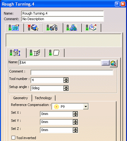
The Reference
Compensation option is defined in the Tool Assembly tab
![]() in the Tooling page
in the Tooling page
![]() .
.

The Gauge values are defined for the specified tool compensation
point (for example, P3).
When the active tool compensation point is different from the reference tool
compensation point (for example, P4), then output parameters of the gauges are
computed according to the tool insert geometry.
All insert types (round, diamond, square, triangular, trigon, and groove) are
supported for computed parameters.
The Reference Compensation option is also available
for a Lathe Tool Change in the Tool Assembly tab
![]() of the tool change editor (see
Inserting Tool Changes for more information).
of the tool change editor (see
Inserting Tool Changes for more information).

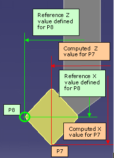
On the tool assembly, reference compensation is defined for
P8 compensation point and gauges (set X, set Y, set Z values) are defined for
this point.
When using another active compensation (Tool compensation defined in Strategy
page
![]() )
(P7 point), the computed X, Y and Z gauges are output according to this point
(P7 point).
)
(P7 point), the computed X, Y and Z gauges are output according to this point
(P7 point).

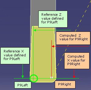
On the tool assembly, reference compensation is defined for
P9Left compensation point and gauges (set X, set Y, set Z values) are defined
for this point.
When using another active compensation (P9Right point), the computed X, Y and
Z gauges are output according to this point (P9Right point).
The following parameters allow you to output the gauge values corresponding to the active tool compensation point.
MFG_CMP_TL_SET_X: Computed Tool Assembly set length in X direction
MFG_CMP_TL_SET_Y: Computed Tool Assembly set length in Y direction
MFG_CMP_TL_SET_Z: Computed Tool Assembly set length in Z direction
MFG_CMP_NOSE_RADIUS: Nose radius corresponding to the active compensation point
(left or right). Nose radius could be different for groove insert (left radius,
right radius), when changing the active compensation point automatically. For
other inserts (diamond, square, and so on) the value is the insert radius.
These parameters can be defined in NC_TOOL_CHANGE_LATHE or NC_CHANGE_REF_PT NC commands (see PP Tables and PP Word Syntaxes) for more information.
Example of NC_CHANGE_REF_PT NC command defined in a PP word table:
SWITCH/%%MFG_TL_COMP,%MFG_CMP_TL_SET_X, %MFG_CMP_TL_SET_Y,%MFG_CMP_TL_SET_Z,%MFG_CMP_NOSE_RADIUS
Valuation of the syntax:
SWITCH/9,55.000,0.000,23.000,0.5
These parameters are computed for the active tool compensation point defined on the turning operation according to the tool geometry.
Tool Assembly created prior to V5R18:
When editing the tool assembly, the Reference Compensation option
is initialized to P9 compensation point. This option can be modified to define
the reference compensation point for the set length values.
Previous parameters MFG_TL_SET_X, MFG_TL_SET_Y, MFG_TL_SET_Z and MFG_NOSE_RADIUS still exist. Valuations are done according to the gauges defined on the lathe tool assembly (without any computation). The reference tool compensation point is not taken into account to compute these parameters.
Recommendation is to use the computed parameters described in Output File in the NC commands.