|
|
This task shows you how to edit an insert
holder that is already used in your document. Note that if you edit a resource that is used by one or more machining operations, then these operations will be impacted by the modification. |
|
|
|
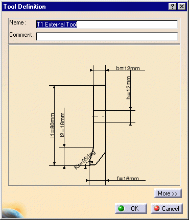
1. | Double-click the desired
insert holder in the Resource List. You can also right-click it and select the Edit NC Resource contextual command. |
| The Tool Definition dialog box is displayed allowing you
to edit the insert holder's geometric, technological, and compensation
parameters. |
||
|
|
Please refer to Tools/Insert Holders for Turning Operations for a description of the available parameters for this resource. | |
| 2. | If needed, enter a new name and comment for the insert holder. | |
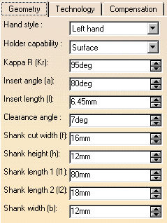
| 3. | Click More to expand the dialog box to access the Geometry, Technology, and Compensation tabs. | |
| 4. | You can specify the insert holder geometry in two ways:
The icon representation of the insert holder is updated with these values. |
|
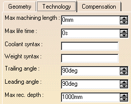
| 5. | Click the Technology tab and enter the desired
values for the insert holder's technological parameters. |
|
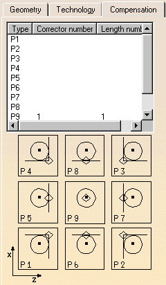
| 6. | If cutter compensation is required, click the
Compensation tab.
You can either edit an existing compensation site or add another site, if other sites are proposed. |
|
| 7. | Right-click the desired line to either edit or add
cutter compensation data. The Compensation Definition dialog box appears. |
|
| 8. | Enter the desired values for the cutter compensation
sites.
See Specify Tool Compensation for more information. |
|
| 9. | Click OK to accept the modifications made to the insert holder. | |
|
|
A CATPart or CATProduct
representation can be assigned to the insert holder by means of the
Add User Representation contextual command in the Resource
List.A mask symbol on the bottom right of the Insert Holder icon in
the PPR tree indicates that a user representation has been added to the
resource. For example: For more information about user representations, please refer to User Representation of Lathe Tools. |
|
|
|
||