![]()
This task shows how to convert constraints into joints in advanced mode. Prior to performing this scenario, you should be familiar with assembly constrains conversion in beginner's mode.
The Assembly Constraints Conversion capability enables only basic joints to be created from constraints (revolute, cylindrical, rigid, planar, spherical and prismatic).
![]()
Open the
jigsaw_with_constraints.CATProduct document.
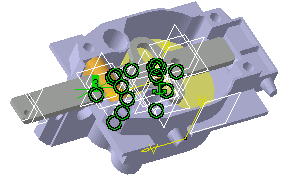
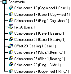
The constraints are visible both in the geometry area and in the
specification tree:
|
|
|
|
-
Click Assembly Constraints Conversion
 in the DMU Kinematics toolbar.
The Assembly Constraints Conversion dialog box appears:
-
Click the New mechanism.
-
Click
 .
.
The Assembly Constraints Conversion dialog box expands: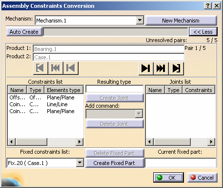
Let's look at this dialog box more carefully:
 :
specifies the status of the product pairs
Shows the pair comprising of two products (Bearing.1 and Case.1). You are dealing with the first pair (1/5).
The Constraints list displays:
-
the name and type of the constraints,
-
the elements type and detailed information about the first and second element.
The joints and Fixed constraints lists display the same kind of information.
Run the Assembly constraints conversion using one of the VCR buttons:
-
 : lets you step forward.
 -
 : lets you go to next unresolved pair.
 -
 : lets you go to the last pair.
-
-
Click Create Fixed Part button to create the fixed part. The fixed part is visible in the Current fixed part field.

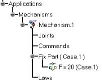
The fixed part is identified in the specification tree and highlighted in the geometry area.
You are now ready to convert assembly constraints into joints for the first pair of products namely Bearing.1 and Case.1 -
Multi-select Offset.23, Coincidence.21 and Coincidence.22 in the Constraints List (use CRTL Key + left mouse button).
The Create Joint button is no longer grayed out.
Click
 (the resulting
type is specified in the resulting type field).
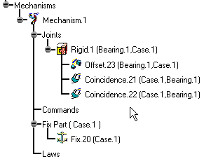
The Joint list is updated. If you are not satisfied, click the Delete Joint button.The rigid joint is identified in the specification tree and highlighted in the geometry area
-
Proceed in the same manner to convert the remaining assembly constraints into joints. Use Go to Next Unresolved button :

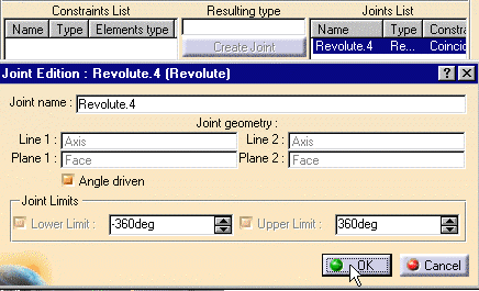
You converted the constraints but forgot to create a command. You need to assign the command to Revolute.4
Use Step Backward button
-
All you need to do is double-click Revolute.4 in the Joint list and select the Angle driven check box in the Joint Edition dialog box displayed.
-
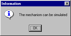
Click Ok in the Joint Edition dialog box. When done click OK. The following information message is displayed:
-
Click OK to confirm your operation.
The mechanism can now be simulated.
-
Click the Simulation with commands icon
 in the DMU Kinematics toolbar.
Refer to Simulating with Commands.
![]()
Note: when you have several fixed constraints in your assembly, you can create a rigid joint between each of them. When this is the case, the following warning is displayed:
|
|
![]()
