Speed and Accelerations Measurement
Capability
- Measuring speed and accelerations during mechanism operation is useful to study a mechanism behavior and/ or to improve its design.
- Two types of speeds and accelerations can be measured:
- Linear speed and acceleration calculations based upon a point with respect to a reference product
- Angular speed and acceleration calculations of the product to which the point belongs.
- Result projection is calculated either with respect to:
- The main axis or,
- The other axis (Cartesian system axis)
How to access this capability?
Clicking the Speed and Acceleration icon
![]() in the DMU
Kinematics toolbar.
in the DMU
Kinematics toolbar.
The Speed and Acceleration dialog box automatically appears
Step-by-Step Scenario
In our example we define speeds and accelerations:
- on a point belonging to the output shaft (Eccentric_Shaft) with
respect to the main frame.
- on another a point belonging to the exit shaft (Exit_Shaft) with
respect to the main frame
To simplify the results, we assume the shaft has a translation movement, therefore the results will be projected onto an axis system belonging to the main frame (z axis is co-linear with respect to the exit shaft axis)
-
Select the mechanism on which you want to define speeds and acceleration specification
i.e. select Mechanism.1 in the specification tree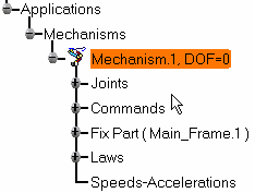

Note: the degree of freedom of the mechanism displayed by default, if you want to hide it, right-click the mechanism and select Hide degree of freedom item from the contextual menu displayed 
-
Click Speed and Acceleration
 in the DMU
Kinematics toolbar. The Speed and Acceleration dialog
box appears.
 -
(Optional)
Enter a meaningful name. In our example keep the default name which is: Speed-Acceleration1 -
Click once in the Point selection field and select a point belonging to the parts involved in the mechanisms.
i.e. select Point.1 under Eccentric_Shaft either in the specification tree or in the geometry area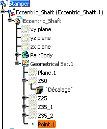
Note: The speeds and accelerations of this point (sensor) will be calculated with respect to a reference product
-
Click once in the Reference product field and select the reference product of your choice
i.e. select Main_Frame.1 either in the specification or in the geometry area.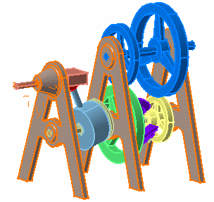
-
Select an axis system for the projection of the result. In our example, keep the default one which is the root product axis system.
-
Click Ok in the Speed and Acceleration dialog box
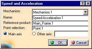
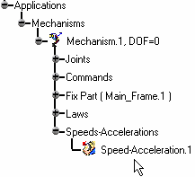
The Speed-Acceleration.1 item is identified in the specification tree.
-
Repeat Step 2.
-
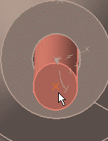
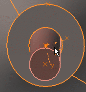
Click once in the point selection field and select Point.2 under Exit_Shaft either in the specification tree or in the geometry area
-
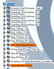
Click once in the Reference product field and select Main_Frame.1 either in the specification or in the geometry area.
-
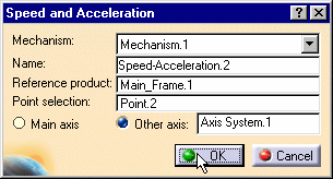
Select a Cartesian axis system for the projection results.
Select the Other axis option, click once in the field and select Axis System.1 under Main_Frame.1.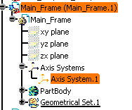
-
Click Ok to create the Speed-Acceleration.2 object.
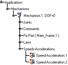
The Speeds and accelerations are identified in the specification tree.
-
Click Simulation with Laws
 in the DMU Kinematics toolbar.
 -
Select the Activate Sensors option to display all measures during simulation.
-
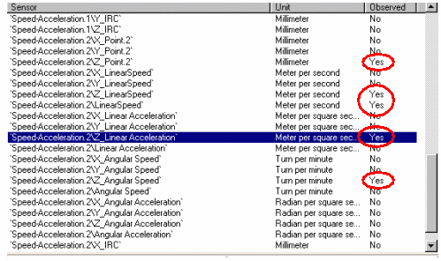
Select the sensors to be observed:
- Speed-Acceleration.1\\X_AngularSpeed
- Speed-Acceleration.2\\Z_Point.2
- Speed-Acceleration.2\\Z_LinearSpeed
- Speed-Acceleration.2\\LinearSpeed
- Speed-Acceleration.2\\Z_Angular Speed
-
Run your simulation with laws
-
The Speed and Acceleration result parameters are logged (22 Measures are available, including linear and angular speed and acceleration (their projections on the reference axis chosen and their magnitude. Besides, the coordinates of the computation point are available too.
-
Click the Graphics button from the outputs area to obtain a graphical representation

-
Click Close.
-
Open MeasureSpeedAcceleration_Result.CATProduct document to check your results.
Related topics
![]()