Before You Begin
Structure of the standard is defined by the administrator.
A standard file is structured as a tree, as it appears in the
Standards Editor
(available via Tools > Standards).
It contains several main sections, each dealing with a specific aspect of
the customization:
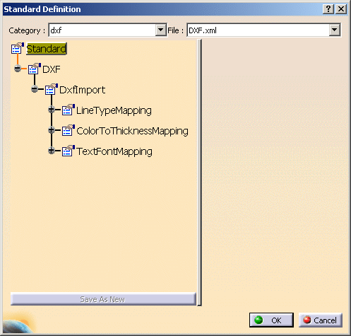
e.g. for DXF:

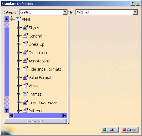
e.g. for Drafting:

Setting Mapping Parameters
This scenario provides an example of Line Type mapping but the procedure is the same when
customizing other parameters.
The lists of attributes are not the same in
V5 and AutoCAD.
Mapping options are used to come as close as possible to the AutoCAD
attributes,
or to switch them to V5 attributes.
- A default mapping is available, but you can customize the mappings
according to your needs,
and create many new DXF mapping standard files. - The V5 parameters proposed are those of the current Drafting standard
file.
Refer to Setting Standard Styles in the Interactive Drafting User's Guide for more details. - You should be familiar with the DXF/DWG styles.
- Select AutoCAD colors by their number.
- Select AutoCAD line types by their name.
- Select V5 line types or thicknesses by their number.
- For text fonts you can:
- map any DXF font with a V5 font,
- associate a X scale factor to reframe a font with a different
geometry
(characters too wide or too narrow)
to achieve the best possible alignment , - define a default font to be used when there is no mapping for a DXF font,
- define a default KANJI font, other than SSS4, to be used when the BigFont DXF font is not mapped.
-
You need to work in administrator mode. To do this, proceed as follows:
- Set up the CATReferenceSettingPath variable.
- Start a V5 session using the -admin option.
For more information, refer to the Managing Environments chapter in the Infrastructure Installation Guide.
-
Set the variables CATCollectionStandard and CATDefaultCollectionStandard.
If none of the conditions are respected, a warning message will appear to let you know that you will neither be able to modify nor save the XML files. -
Select Tools > Standards to launch the standards editor.
-
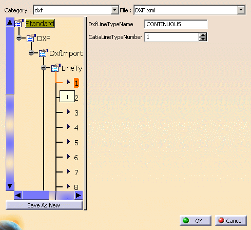
Choose the dxf category, and then open the DXF.xml file from the drop-down list.
Expand the LineTypeMapping node in the editor. -
Select the line type 1 on the left. On the right, its DXF name and CATIA type number are displayed.
Use the spinner to change it to another CATIA type number. -
Repeat this step with the other line types.
-
Click OK to save your modifications in the current file and exit the standards editor
or Create a new mapping standard file using the File - > Save as New command.
Call it DXFDoc.xml in the directory.
If you have created a new DXF mapping standard file, it is now available in the drop-down list in the DXF settings
(available through Tools/Options/General/Compatibility)

 |
![]()