V5 standard parameters need to be properly defined (as in V4) in order for the migration result to be equivalent to the original V4 2D Model.
- how the migration of 2D Draw elements (dimensions, texts, arrows, lines and patterns) is carried out,
- and what you need to pre-define concerning the V5 standard parameters before starting the migration process.
About V4 to V5 Standards Management
When managing standards for V4 to V5 migration, you will need to bear the following information in mind:
- As in V4, it is a CATIA administrator who manages V5 standards definition.
- In V5, standards are defined via the Standards Editor: Tools > Standards, Drafting category.
- A complete standard definition is stored in a XML file. For example, ANSI.xml defines the ANSI standard.
- In V4, a .Model can mix different standards whereas in V5, a .CATDrawing is mono-standard: when a new .CATDrawing is created, only one standard defined in the Standards Editor (and stored in a single XML file) can be referenced and is embedded in the .CATDrawing.
- Whatever the standard of the V4 view was prior to being copied into CATIA Version 5, once in V5, the standard is that selected when you open the .CATDrawing document.
For more information, refer to the Administration Tasks chapter in the Interactive Drafting User's Guide.
Referencing the Project File (PRJ)
Before starting the migration process, you need to reference in V5 the project file (PRJ) used to create the V4 2D model. To do this, go to Tools > Options > General > Compatibility > V4 Data Reading tab, and fill in the PROJECT File Patch and DLNAME fields.
 |
About 2D Migration Methodology
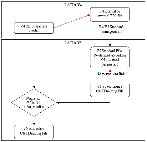
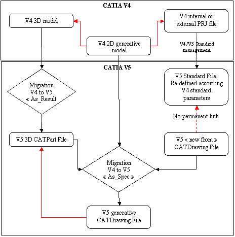
The methodology which is applied when migrating 2D Interactive and 2D Generative drawings is shown in the charts below.
V4 to V5 2D Interactive Drawing Migration
 |
V4 to V5 2D Generative Drawing Migration
 |
Standard Parameters
You can manage the following V5 standard parameters in preparation for V4 to V5 migration of 2D Draw elements:
![]()