 |
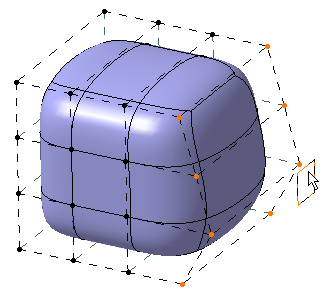
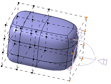
This task shows you how to re-organize the vertices of a mesh. |
 |
Open the Aligning2.CATPart
document. |
 |
-
Click Modification
 and select the surface.
 |
You can also access this command by
pressing ALT+SHIFT+M. |
-
Click Alignment
 . .
 |
You can also access this command by
pressing CTRL+SHIFT+Q. |
When the Alignment command is activated, three
new icons appear in the Tools Palette:
 |
| The following icons let you: |
-
 project
vertices onto the axis of the compass. When this option is
activated the following options are available for surface
selection: Edge Selection,
Vertex Selection, All
Elements Selection. project
vertices onto the axis of the compass. When this option is
activated the following options are available for surface
selection: Edge Selection,
Vertex Selection, All
Elements Selection.
|
-
 project
vertices onto the plane of the compass. When this option is
activated the following options are available for surface
selection: All Type Selection,
Face Selection,
Edge Selection,
Vertex Selection,
All Elements Selection. project
vertices onto the plane of the compass. When this option is
activated the following options are available for surface
selection: All Type Selection,
Face Selection,
Edge Selection,
Vertex Selection,
All Elements Selection.
|
-

|
| The other icons let you filter the type of association:
surface, edge or vertex. |
-
Click Compass Definition
 to define the compass' position.
-
Click Compass Definition
 again.
|
| |
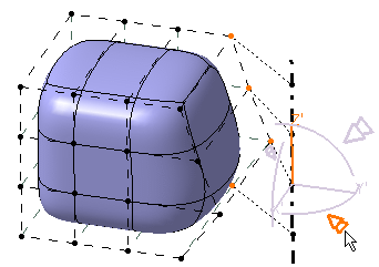
Projecting onto the axis
|
| |
-
Click Projection on Line
 . .
-
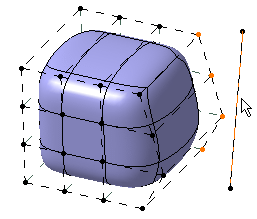
Select elements to be projected.
-
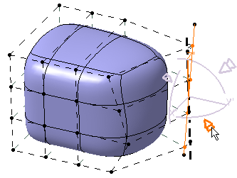
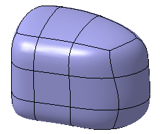
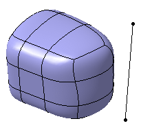
Click on the manipulator arrow depending on the direction where you want
to align the vertex.
In this case, click on the interactive arrow as shown below:
-
|
|
 |
|
| |
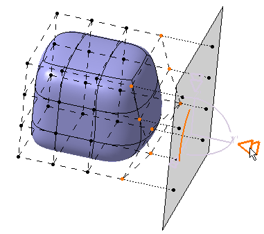
Projecting onto the plane
|
| |
-
Click Projection on Plane
 . .
-
Select elements to be projected.
-
-
|
|
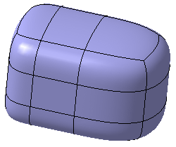 |
|
| |
Using Pick
|
| |
-
-
-
-
-
|
|
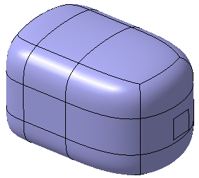 |
-
-
-
-
-
|
|
 |
|
|
 |
-
|
|
 |
-
-
-
-
|
|
 |
 and select the surface.
 .
.

 project
vertices onto the axis of the compass. When this option is
activated the following options are available for surface
selection: Edge Selection,
Vertex Selection, All
Elements Selection.
 project
vertices onto the plane of the compass. When this option is
activated the following options are available for surface
selection: All Type Selection,
Face Selection,
Edge Selection,
Vertex Selection,
All Elements Selection.
 to define the compass' position.
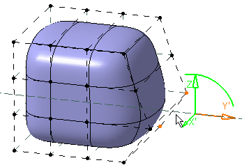
 again.
 .
.

 .
.


![]()
