 |
This task shows you how to place
a hanger in free space. |
 |
After you place a hanger you must
attach it to the surface. See Attaching a Hanger
to learn how to do this.
The Hanger Placement dialog box that is explained here
allows you to perform several functions. You do not need all of them to
place a hanger, but all are explained in this task. |
 |
NOTE: There is a command in the menubar -
Insert > Place Object from Catalog, that can also be used to
place parts. However, the command works differently from the normal Place Part command
described in this task. The command
Place Object from Catalog is meant to be used with parts that
are not typed, and is normally used in spatial products like Plant
Layout. If you use this command to place a part, it will not have
the technology associated with a normal typed part, such as automatic
object naming or resizing capability, nor will it be a unique reference.
A typed part is one that has been assigned a class and sub-class in the
feature dictionary. When you place an object using this command, a unique
reference will be created and placed in the CATTemp directory. The
instance will not point to the catalog. If you want the instance to
point to the catalog reference then you need to add a keyword to the
family to which the part belongs. Add the following to the family, using
the Catalog Editor:
- Name - LoadType;
- Type - String;
- Default Value - SameReference.
To learn how to add a keyword see Creating a Catalog in
the Component Catalog Editor user guide. |

|
1. |
Click the Place Hanger
button  and select the
In Space tab in the Hanger Placement dialog box that
displays. and select the
In Space tab in the Hanger Placement dialog box that
displays.
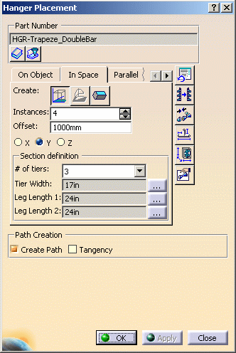
NOTE:
- The Section Definition fields display only if there is a
hanger selected in the Part Number field.
- The Path Creation fields display only when the In
Space, Parallel or Turn tab is selected, AND
the value of the Instances field is more than 1, AND
Offset is more than 0.
|
|
2. |
Click the Open
Catalog Browser button
 (under the Part
Number field) to display the Catalog Browser.
Expand the entries to see the hangers available to you. For this exercise,
select HGR-Trapeze_Adj. The Catalog Browser
closes and the hanger you selected displays in the Part Number
field.

|
|
3. |
If you want to narrow the choices
available, you can use the filter function. To filter, click the
Filter Parameters button
 under the Part
Number field. The Filter Definition dialog box displays. under the Part
Number field. The Filter Definition dialog box displays.
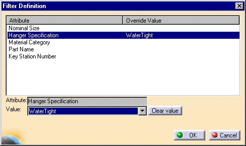
Select an attribute, click on the down arrow in the Value
field and select a value. The value displays in the Override Value column.
Click the Clear Value button if you want to remove it from the column. |
|
4. |
You can use the buttons in the
Create field to place the hanger.
Click the Place on Active Axis Plane ... button
 to place along the X,
Y or Z axis. Select the required axis in the dialog box.
 |
|
|
The Place on Compass Plane...
button  is used in special
circumstances. Normally when you place a hanger on a surface, you use the
Place on Surface button described below. There may be circumstances,
however, where you may want to use the compass for added flexibility in
placement.

|
|
|
Click
the Place on Surface
... button  to place
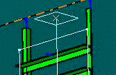
the hanger at an indicated location. When you click this button, a white
square accompanies your mouse pointer. Position this square at the
location you want to place the hanger and click to place it. to place
the hanger at an indicated location. When you click this button, a white
square accompanies your mouse pointer. Position this square at the
location you want to place the hanger and click to place it.
|
|
5. |
In the Instances field,
enter the number of instances of the hanger you want to place. |
|
6. |
In the Offset field,
enter the distance between each instance of the hanger. |
|
7. |
Use the
Section Definition portion to define the size of the hanger.
Click on the down arrow next to the Number of Tiers field and select a
number.
Click on the buttons next to the Tier Width and Leg Length fields and
select a value in the tables that display. Check the Use as Default
checkbox to use these values as the default hanger size. |
|
8. |
The
Attach Downcomer button
 lets you attach
selected hangers to the surface you have placed them on. All hangers
placed during the current session are selected by default. See
Attaching a Hanger for more information. lets you attach
selected hangers to the surface you have placed them on. All hangers
placed during the current session are selected by default. See
Attaching a Hanger for more information. |
|
9. |
The Edit Parameters
button  lets you
change the parameters of selected hangers. All hangers placed during the
current session are selected by default. See
Change the Parameters of a Part for more information. lets you
change the parameters of selected hangers. All hangers placed during the
current session are selected by default. See
Change the Parameters of a Part for more information. |
|
10. |
The
Flip Hanger function
 allows you to change the
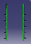
direction in which the tiers overhang. Clicking the Flip Hanger
button changes the direction of overhang in the selected hanger(s) as
shown in the image below.
|
|
|
11. |
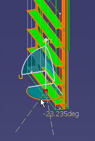
The
Translate/Rotate Hanger
 button places the compass on the hanger.
Click on the arc of the compass and drag to rotate the hanger. You can
also move the hanger along a line, the manipulation lines on a compass or
surrounding box, for instance.
|
|
12. |
Click the
Set Attributes button
 to
assign
values to attributes during hanger placement. A list of attributes and
values displays in a box at the bottom of the Hanger Placement dialog box. to
assign
values to attributes during hanger placement. A list of attributes and
values displays in a box at the bottom of the Hanger Placement dialog box.
NOTE:
- Attributes/Values display only when Part Type is a Rack.
- The Set Attributes button is not active until you define the
Instantiating Attributes. See Adding
Instantiating Attributes.

Select an attribute in the Attribute column and the
Select Option box displays.
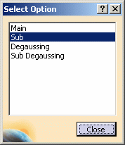
Select a value from the list and the selected value displays in the
Value column (in the first box). Repeat for each attribute and value. |
|
13. |
Click at a location to place the
hanger. |
 |
|
Clicking
the Reset Tab Page
button  resets all the
fields in the dialog box. resets all the
fields in the dialog box. |
|
14. |
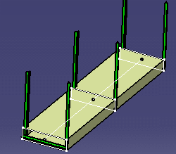
You
can create a lofted pathway
without having to open the Systems Space Reservation application. Check
the Create Path checkbox before you click Apply or
OK to create the lofted pathway when the hangers are placed.
See Systems Space Reservation documentation for more information about
lofted pathways.
|


![]() to place along the X,
Y or Z axis. Select the required axis in the dialog box.
to place along the X,
Y or Z axis. Select the required axis in the dialog box.


