eventually re-orient faces to be used in the Join action afterwards.
More Operating Mode information is available in the Face Orientation Basic Task.
Main dialog box
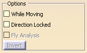
Options

Updates the display of the orientation of the faces while
the object selected is moved.
This check box is not selected by default.
Enables you to navigate into the model without modifying the
display of the orientations
when the screen direction is modified.
This check box is not selected by default.
Available only if the Direction Locked check box is
selected.
Displays an arrow under the pointer, identifying the normal
to the face at the pointer location
while you move the pointer over the face.
Furthermore, circles are displayed indicating the plane tangent to the face
at this point.
Opens a dialog box to invert the orientation of one or several faces.
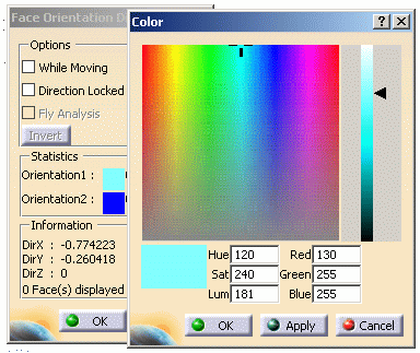
Statistics

The orientation of the faces is computed with respect to the
normal to the screen.
Faces are displayed as facets.
One face may be made of several facets, that have not necessarily the same
orientation.
This number depending on the orientation of the model.
Statistics displays the number of facets found in each
orientation direction.
Those facets are displayed in two different colors.
Double-click the color patch to change this color in the
color editor.

Information

Displays the three axes of the current view direction and the number of faces displayed.
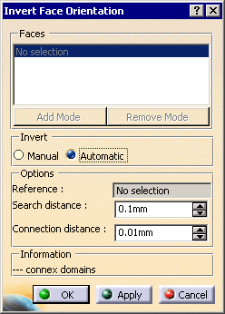
Face Invert Orientation dialog box

Faces
Lists the elements selected for re-orientation.
In the Manual mode, you can edit the list of elements to be
inverted:
- by selecting elements in the geometry:
- Standard selection (no button clicked):
- when you select an unlisted element, it is added to the list
- when you select a listed element, it is removed from the list
- when you select an unlisted element, it is added to the list
- when you select a listed element, it remains in the list
- when you select an unlisted element, the list is unchanged
- when you select a listed element, it removed from the list
If you double-click Add Mode or Remove Mode, the
chosen mode is permanent,
i.e. successively selecting elements will add/remove them.
However, if you click only once, only the next selected element is added or
removed.
You only have to click the button again, or click another one, to deactivate the mode.
- by selecting an element in the list then using the Clear Selection contextual menu item to remove it from the list.

In Automatic mode, once the reference element has been
selected, the faces to re-orient are listed automatically.
This list can not be edited.
Invert
Proposes two invert orientation modes:
- Manual: you select the face(s) to re-orient.
- Automatic: you select a Reference element that defines the faces to re-orient.
Options
Available for the automatic mode only.

The name of the face selected as reference appears in this field.
If you want to change that reference, place the cursor in this box and
select another face in the graphic area.
Defines the domain in which the action searches edges that might be
merged.
The higher the search distance, the higher the number of candidate edges.
Distance below which two elements are considered as identical.
Search distance and Connection distance aim at
defining a single connex domain.
You can use the Surface Connection Checker to
determine those distances.
Information
![]()
Used for the automatic mode.
This field displays information on the number of connex domains found.
If there are several, only the one containing the reference element will be
processed.
Use the Search distance and the Connection distance
above to obtain only one domain.