- with respect to given conditions,
- by analyzing the model to find connexity problems.
You can then:
- order in bodies the sites of the model that should be healed, by importance or location.
More Operating Mode information is available in the Surface Connection Checker Basic Task.
Analysis conditions

Defines the domain in which the action searches edges that might be
merged.
The higher the search distance, the higher the number of candidate edges.

Two predefined search distances are proposed:
- Regular: this is the default value, set to 0.1 mm
- Quick: set to 0.001 mm
Those values are displayed only as information and can not be edited.
![]()
User lets you enter your own search distance: the value field becomes editable.
If the Internal edges check box is selected, the analysis will
be done on the faces,
if it is not selected the analysis will be done on the surfaces.
- Click Apply after any modification of one of these parameters to restart the analysis.
This field is updated as soon as you select faces or modify the selection (no need to click Apply)
This field is updated after each Apply.
Results
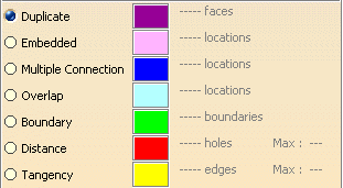
Eventual connection problems are listed:
- Duplicate: Duplicate faces, with their number,
- Embedded: Number of locations where one element is completely included in another one,
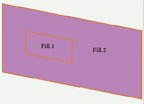
- Only faces with the same support may be recognized as embedded.
- To ensure correct time performances, the search for embedded faces is
done on a sampling.
Therefore, some faces may be recognized as embedded whereas they are not.
- Multiple Connection: number of locations where elements have multiple connections,
- Overlap:
number of locations where one element covers a portion of another one,
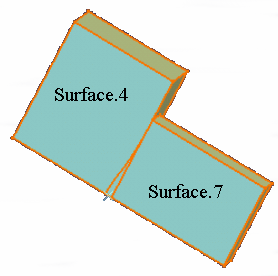
- Sometimes, a visual analysis of the faces may be deceptive: one face
seems to overlap another one.
However no overlap is detected by the Surface Connection Checker.
This is due to the fact that a distance gap exists in the boundary of the first face.
Due to this gap, those faces are not overlapping each other and no overlap is detected.
Therefore, we would recommend to check the model for distance gaps before searching overlapping faces. - The overlaps detected are those that lead to a bad orientation of the
model.
Therefore overlaps are detected only if the angle formed by the normals of the faces is greater than 135 degrees.
- Boundary: number of boundaries found.
- Distance: number of holes found and their maximum value,
- Tangency: tangency anomalies and their maximum value,
Locations are graphically highlighted in the viewer:
- sequentially as you select the lines,
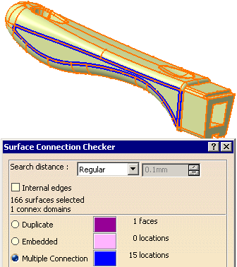
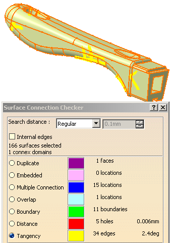
- with the color displayed beside the label. Double-click the color
patch to change this color in the
color editor.
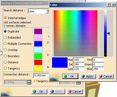
Analysis tune-up

Once a first analysis has been completed, you can examine the anomalies
more thoroughly by modifying those parameters.
Click Apply after each modification to restart the computation
and update the information in the viewer and in the dialog box.
Distance below which two elements are considered as identical.
Tangency errorAvailable when the line Tangency is selected. Defines the angle interval taken into account to find tangency anomalies.
TransferClick Transfer to start the Transfer
dialog box. The transfer applies to the problems corresponding to the selected line,
e.g. if Tangency is selected, only tangency anomalies are
listed in the Transfer dialog box.
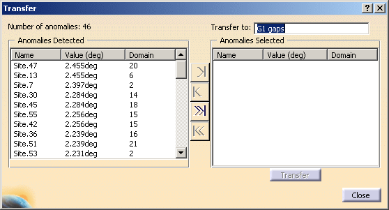
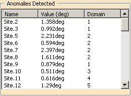
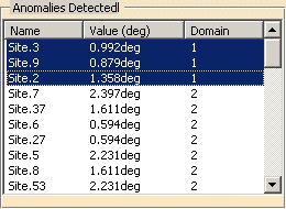
On the left, you will find information on the anomalies found:
- their number (Number of anomalies),
- their Name (Site.xx, Site being a set of two defective faces),
- the Value of the gap,
- the numerical name of their Domain (Domain is a set of several defective faces).
By default, the anomalies are ordered in decreasing gap value order.
You can order them by name or by domain by clicking on the column title.
Ordering the anomalies enables you to isolate and transfer the anomalies
found in one site or one domain,
or according to the value of the gap, in the same body.
|
|
transfers the selected line(s) from Anomalies Detected to Anomalies Selected | |
| transfers the selected line(s) from Anomalies Selected to Anomalies Detected | ||
| transfers all the line(s) from Anomalies Detected to Anomalies Selected | ||
| transfers all the line(s) from Anomalies Selected to Anomalies Detected |
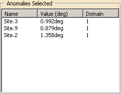
On the right, you have the information on the transfer:
- Transfer to proposes the name of the body where the defective face will be transferred:
| Duplicate faces | for | Duplicate | |
| Embedded cases | for | Embedded | |
| Multiple connection cases | for | Multiple connection | |
| Overlap cases | for | Overlap | |
| Boundaries | for | Boundary | |
| G0 gaps | for | Distance | |
| G1 gaps | for | Tangency |
Those names are editable. One body is created for each Transfer.
If you transfer the anomalies of one type in several shots, several bodies will be created, their name being incremented.
- Anomalies Selected lists the elements to be transferred.
- Transfer starts the transfer and let the dialog box open for another transfer.
- Close starts the current transfer, closes the dialog box and reverts to the main dialog box.
- The faces are transferred to the body(ies) and hidden in the model. This isolates the defective faces that can be healed later on.
![]()
A contextual menu
Reframe On is
available on each anomaly listed in the transfer dialog box.
The zoom factor is set automatically according to the size of the smallest
element.
It also works on assembled surfaces. Each face concerned appears in another
color.
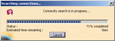
- Gives you the status of the analysis,
- Enables you to cancel the analysis by clicking Cancel.