Open the Constraint1.CATPart document.
Make sure the Constraints option is checked in Tools > Options > Infrastructure > Part Infrastructure > Display tab, so that you are able to see the constraints in the specification tree.
-
Click the Matching Constraint icon:

The Match Constraint dialog box displays. 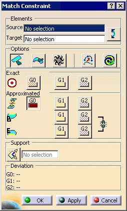
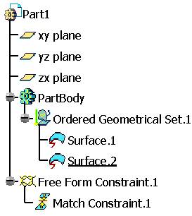
In the Match Constraint dialog box you can:
- Elements: manages elements involved in the continuity
constraint:
- Source: the element to be deformed; an edge for surface matching, a vertex for curve matching.
- Target: the reference element; an edge, a plane, a curve or a vertex
-
 Swap: swaps the source and target elements.
- Options:
-
 Partly: the matching surface meets the edge of the reference surface
partly, manipulators appear to move the two meeting points.
 -
 Inside: projects the boundary on the target surface.
This option is only available if Exact is not selected. -
 Diffusion: modifies a maximum of ranks of control points in the element
to be deformed, otherwise only the first rank is modified.
 -
 Adapt: adapts the transversal order of the surface to be matched with
the transversal order of the target surface.
This option is available only of the target edge is an isoparametric of its support surface. -
 Auto Apply: performs the deformation of the surface to be matched each
time you modify an option.
-
- Continuities: there are two types of algorithm that can be used
together; the exact algorithm and the approximated algorithm.
If both of them are used, the first one to be performed is the exact one, then the approximated.- Exact: the first rank of control points of the element
to be deformed takes a regular distribution according to the target
element. Other ranks keep their distribution.
Available orders of continuity for this algorithm are:-
 /
/ G0 (selected/unselected)
 -
 /
/ G1 (selected/unselected)
 -
 /
/ G2 (selected/unselected)
-
- Approximated: the distribution of the first rank of
control points of the surface to be deformed is kept as is.
Other ranks keep their distribution.
Available orders of continuity for this algorithm are:-
 /
/ G0 (selected/unselected)
 -
 /
/ G1 (selected/unselected), only for the start and the end of
the edge.
 -
 /
/ G2 (selected/unselected) only for the start and the end of
the edge.
 -
 /
/ unlink/link orders of continuity for the start and the end of the edge.
-
- Support: defines when selected the normal along which control points can be moved, a contextual menu on the selection field offers creation commands and main axes selection, otherwise the local normal of the target element is taken into account.
- Deviations: displays the deviations according the orders of continuity.
- Exact: the first rank of control points of the element
to be deformed takes a regular distribution according to the target
element. Other ranks keep their distribution.
- Elements: manages elements involved in the continuity
constraint:
-
Select the edge of the surface to be matched.
The boundary is highlighted. 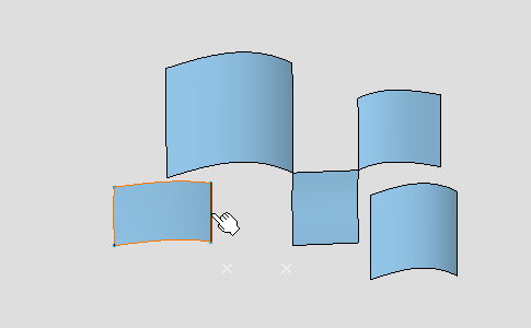
-
Move the pointer onto the second surface.
-
Click the surface when the adequate boundary is highlighted.
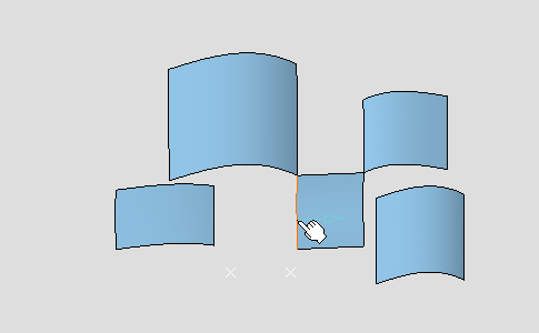
Because the Partly option is selected, two green manipulators represent the projection of the source element onto the target element.
These manipulators can be moved along the edge.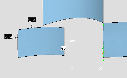
-
Click Apply.
The surface is modified according to the options. 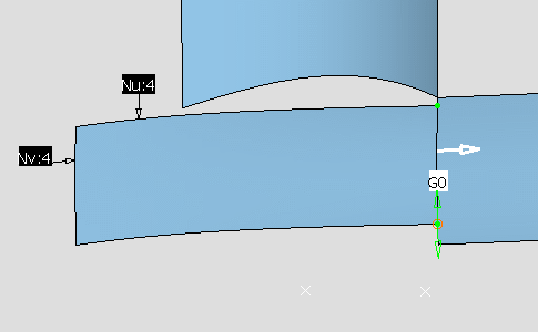
-
Unselect the
 Partly option and click Apply again.
The surface is modified on all the edge. 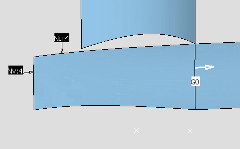
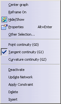
Right-click the continuity type to display the contextual menu, you are able to: - Modify the chosen type: Point continuity (G0), Tangent continuity (G1) or Curvature continuity (G2)
- Activate/Deactivate: activates/deactivates the constraint
- Update Network: updates the constraints linked ones with the others, from the selected constraint and while taking into account their creation order.
- Apply Constraint: updates locally the constraint.
- Delete the constraint.
-
Click OK in the Match Constraint dialog box.

Click the OK button does not perform the Apply operation! -
Create several constraints like these.
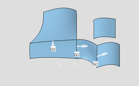
-
Right-click the G0 (tangent) continuity as show and change the continuity type to G2 (Curvature).
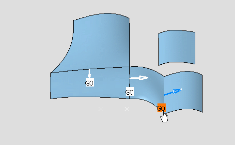
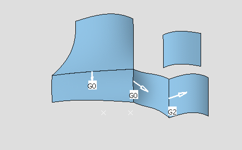
-
Click the G2 (Curvature) continuity arrow to reverse the direction of the constraint.
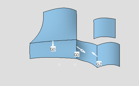
-
Right-click a G0 continuity and deactivate it.
Color of the continuity indicates its activating status: - White, activated.
- Green-yellow, deactivated.
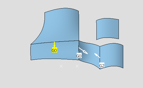
-
Select the Surface.2 and click the Control Points icon
 to display the control points and mesh lines on the surface, allowing you
to dynamically modify them.
to display the control points and mesh lines on the surface, allowing you
to dynamically modify them.The source surface deforms so that the neighboring constraints are automatically updated.
Note that the deactivated constraint is not taken into account.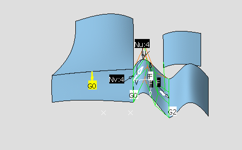

- You can create as many constraints as there are elements.
- You can deactivate the constraints using the Deactivate contextual menu.
- Constraints created using this command are very similar to the constraints created in the Part Design and the Sketcher workbenches: they are compatible and are solved using a variational approach.
-
Click Cancel in the Control Points dialog box.
-
Select the Surface.2 and from the Quick Compass Orientation toolbar, click the In Model or on Perch icon
 to switch the compass from the perch to the selected surface, see
Managing the Compass.
 -
Use the compass to move the surface.
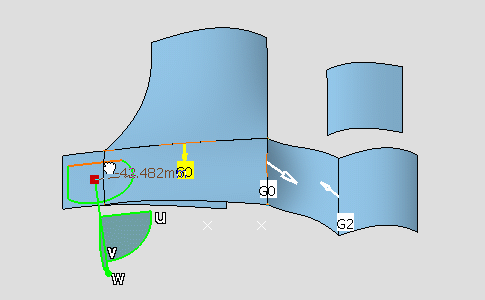
All the constraints are updated accordingly, except the deactivated constraint. 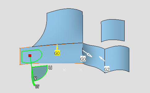

If you wish to delete a constraint, you need to delete it in the specification tree, under the Constraints node. 
Refer to the Constraints chapter in the Part Design documentation and to the Setting Constraints chapter in the Sketcher documentation to have further information. 
Constraints can only be set on datum elements.