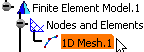
|
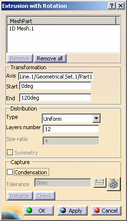
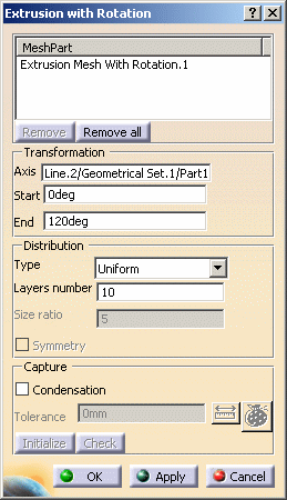
The Extrusion with Rotation dialog box appears.
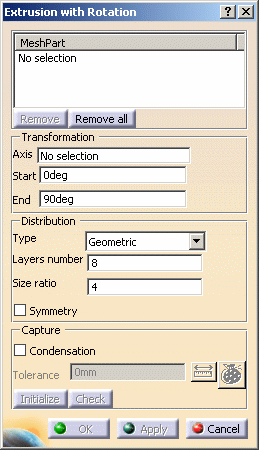
- Mesh Part: lets you specify the mesh part to
extrude.
 |
Multi-selection of mesh parts is available. |
- Remove: lets you remove a selected mesh part from
the Mesh Part field.
- Remove all: lets you remove all the selected mesh
parts from the Mesh Part field.
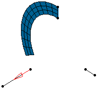
- Transformation
- Axis: lets you specify the axis of extrusion by
rotation.
- Start: lets you specify the start angle value of
the extrusion (in deg).
- End: lets you specify the end angle value of the
extrusion (in deg).
|
|
You can enter a negative value in the
Start and End fields.
|
- Distribution:
- Type: lets you choose the node distribution type:
- Uniform: the distance between all the
distributed nodes will be the same.
- Arithmetic: the distance between the distributed
nodes will be defined by an arithmetical distribution.
- Geometric: the distance between the distributed
nodes will be defined by a geometrical distribution.
- Layers number: lets you specify the number of
layers you want.
 |
Note that the mesh size is variable and
depends on this value and the distance between the source
node and the axis of extrusion by rotation.
For example, if the distribution is uniform, the extrusion
radius value between the source node and the axis of
extrusion by rotation is 40mm, the angle is
45deg and the Layers number value is 10,
the mesh size value will be :
(Angle* Radius) / Layers number =
((PI/4) * 40mm) / 10 = 3.14 mm |
- Size ratio: lets you specify the common difference
value for an Arithmetic distribution or the common
ratio value for a Geometric distribution.
 |
This option is only available if you selected
Arithmetic or Geometric as
Distribution Type option. |
- Symmetry: lets you specify if the distribution
should be symmetric or not.
|
|
This option is only available if you selected
Arithmetic or Geometric as
Distribution Type option. |
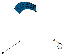
- Capture: a node
capture is automatically done between the parent mesh part and the
extruded mesh part.
- Condensation: if selected, this option lets you
condense nodes of the extruded mesh part and updated neighboring
mesh parts using a tolerance value.
- Tolerance: lets you specify the tolerance value
of condensation (only available with the Condensation
option).
|
|
|
|
 in the Mesh Transformations toolbar.