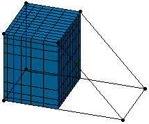
Extruding Mesh Parts by Translation

This task shows you how to extrude a mesh by translation.

You will see here how to:

Create a 2D Mesh from a 1D Mesh

Open the Sample10.CATAnalysis document from the samples directory.

  1. Click Extrude Mesher with Translation in the Mesh Transformations toolbar.

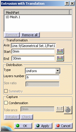
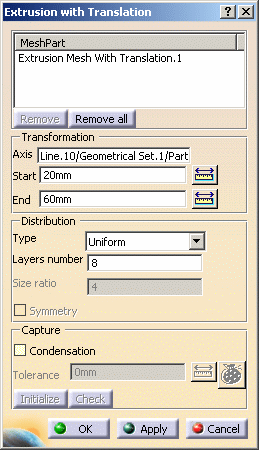
    The Extrusion with Translation dialog box appears.
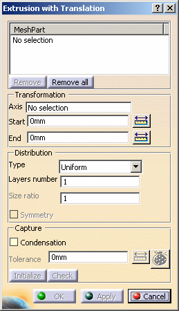
    • Mesh Part: lets you specify the mesh part to extrude.

      Multi-selection of mesh parts is available.

      • Remove: lets you remove a selected mesh part from the Mesh Part field.
      • Remove all: lets you remove all the selected mesh parts from the Mesh Part field.
    • Transformation:
      • Axis: lets you specify the direction of the extrusion.

        A red arrow appears as soon as you have selected the extrusion Axis.

      • Start: lets you specify the start value of the extrusion.
      • End: lets you specify the end value of the extrusion.

        You can enter a negative value in the Start and End fields.

    • Distribution:
      • Type: lets you choose the node distribution type.
        • Uniform: the distance between all the distributed nodes will be the same.
        • Arithmetic: the distance between the distributed nodes will be defined by an arithmetical distribution.
        • Geometric: the distance between the distributed nodes will be defined by a geometrical distribution.
      • Layers number: lets you specify the number of layers you want.

        Note that this value determines the mesh size.
        For example, if the distribution is uniform, the extrusion length value is 30mm and the Layers number value is 6, the mesh size value will be : 30mm / 6 = 5mm.

      • Size ratio: lets you specify the common difference value for an Arithmetic distribution or the common ratio value for a Geometric distribution.

        This option is only available if you selected Arithmetic or Geometric as Distribution Type option.

      • Symmetry: lets you specify if the distribution should be symmetric or not.

        This option is only available if you selected Arithmetic or Geometric as Distribution Type option.

    • Capture: a node capture is automatically done between the parent mesh part and the extruded mesh part on the condition the Start field is equal to 0mm.
      In other words, if the Start field is equal to 0mm, the parent mesh part and the extruded mesh part share the same nodes.
      • Condensation: if selected, this option lets you condense nodes of the extruded mesh part and updated neighboring mesh parts using a tolerance value.
      • Tolerance: lets you specify the tolerance value of condensation (only available with the Condensation option).
      • Initialize: lets you automatically initialize the tolerance value of condensation if the Condensation check box is selected.
        The tolerance is initialized with the smallest size of element edges among all the loaded mesh parts.

        The tolerance initialization does not take into account 1D elements.

      • Check: this button is active as soon as you click the Apply button. This button lets you check, using the tolerance value, if there are intersections or interferences between the extruded mesh and the captured mesh parts (only available with the Condensation option).
        To know more, refer to Checking Intersections / Interferences.
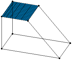
  2. Select 1D Mesh.1 in the specification tree.

  3. Set the desired parameters in the Extrusion with Translation dialog box.

    In this particular example:

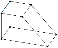
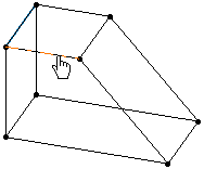
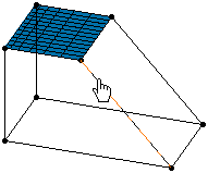
    1. Select Line.9 as Axis as shown below:

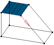
      Note that as soon as you selected the axis, a red arrow appears.
      This arrow indicates the reference direction of the extrusion.

    2. Enter 0mm as Start value.

    3. Enter 30mm as End value.

    4. Select Uniform as Type option.

    5. Enter 6 as Layers number value.

  4. Click Apply.

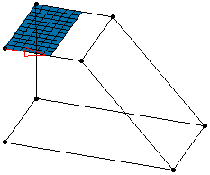
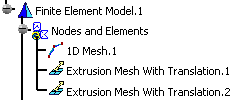
    An Extrusion Mesh with Translation.1 object appears in the specification tree and a 2D extrusion by translation mesh part is created.

  5. Modify the following parameters:

    1. Enter 50mm as End value.

    2. Select Arithmetic as Distribution Type option.

    3. Enter 6 as Layers number value.

    4. Enter 4 as Size ratio value.

  6.  Click Apply and then OK.

    As a result the 2D extrusion by translation mesh part is updated as shown below:


Create a 3D Mesh from a 2D Mesh

You can use the document obtained after performing the Create a 2D mesh from a 1D mesh scenario or open the Sample10_1.CATAnalysis document from the samples directory.

  1. Click Extrude Mesher with Translation in the Mesh Transformations toolbar.
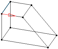
    The Extrusion with Translation dialog box appears.
    For more information about this dialog box, refer to Create a 2D mesh from a 1D mesh.

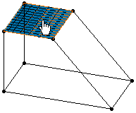
  2. Select the 2D mesh part you want to extrude.

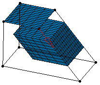
    In this particular example, select the Extrusion Mesh with Translation.1 mesh part in the specification tree or directly from the viewer as shown below:

  3. Modify the following parameters:

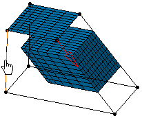
    1. Select Line.10 as Axis as shown below:

      Note that as soon as you selected the axis, a red arrow appears.
      This arrow indicates the reference direction of the extrusion.

    2. Enter 20mm as Start value.

    3. Enter 60mm as End value.

    4. Select Uniform as Type option.

    5. Enter 8 as Layers number value.

  4. Click Apply.

    An Extrusion Mesh with Translation.2 object appears in the specification tree and a 3D extrusion by translation mesh part is created.

  5. Modify the following parameters:

    1. Select the Axis box, then Line.2 as shown below:

    2. Enter 0mm as Start value.

    3. Select Geometric as Distribution Type option.

    4. Enter 8 as Layers number value.

    5. Enter 4 as Size ratio value.

    6. Select the Symmetry check box.

  6. Click Apply and then OK.

    As a result the 3D extrusion by translation mesh part is updated as shown below: