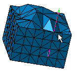
The tetrahedron filler provides volume mesh (Linear Tetrahedron or Parabolic Tetrahedron - cf. Finite Element Reference Guide) from surface mesh (Linear Triangle Shell or Linear Quadrangle - cf. Finite Element Reference Guide).
-
This functionality is only available with the FEM Solid (FMD) product.
-
There are two necessary conditions to generate a solid mesh:
- Make sure that the mesh surface is closed in terms of connectivity.
- Make sure that the surface mesh has no intersection.
To do this, refer to Checking Intersections / Interferences.
Moreover the quality of 3D mesh depends on the quality of the 2D mesh. Make sure that the quality of the surface mesh you will use to generate the 3D mesh is good.
- A surface mesh must exist and can be associated or not to a geometry.
If the surface mesh is associated to a geometry, this geometry can be either a solid or a set of connected faces.- Open the sample40.CATAnalysis document from the samples directory.
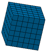
In this particular example, a surface mesh has been already created.
-
Click Tetrahedron Filler
 in the Meshing Methods toolbar.
The Tetrahedron Filler dialog box appears.
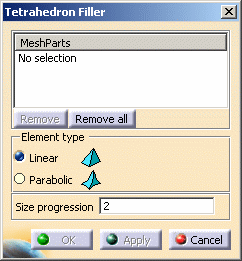
- MeshParts: lets you select 2D mesh parts you will
use to generate the 3D mesh.

Multi-selection of 2D mesh parts is available.
You can select Surface Mesh part, Advanced Surface Mesh part, Octree Triangle Mesh part, Coating 2D Mesh part or all 2D mesh parts created using the Transformation functionalities.- Remove: lets you remove a selected mesh part.
- Remove all: lets you remove all the mesh parts.
- Element Type: lets you choose the type of solid mesh
elements. They are independent of the surface mesh elements degree.
- Linear: elements without intermediate nodes, useful to fill a solid with only straight edges.
- Parabolic: elements with intermediate nodes on the
geometry, useful to fill a solid with curve edges.
Linear elements type:
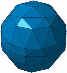
Parabolic elements type:
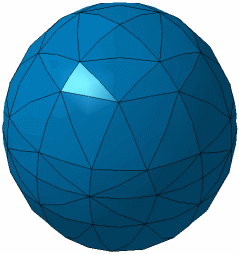
- Size progression: factor which lets you dilute the mesh elements inside the solid (if this factor is equal to one, the internal edge sizes are the sizes induced from the surface edge sizes).
- MeshParts: lets you select 2D mesh parts you will
use to generate the 3D mesh.
-
Select the desired options.
In this particular example, select the Advanced Surface Mesh.2.
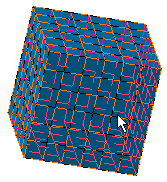
The dialog box is updated:
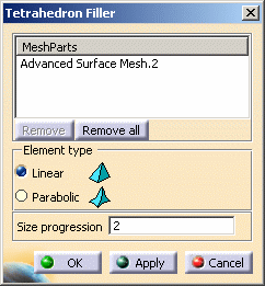

In the case of a set of connected surface meshes, you have to select different surface mesh parts until the global surface mesh is closed (free edges appear in green while the global surface mesh is not closed).
-
Select the Element type option and the Size progression factor.
In this particular example, select the Linear option and 2 as Size progression factor.
-
Click Apply.
The corresponding quads are automatically split into two triangles using the shortest diagonal. This operation is only a preprocessing of Tetrahedron Filler: the original quads are preserved in the mesh model.
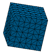
The mesh is generated on the part and the Tetrahedron Filler Mesh.1 appears in the specification tree.
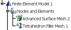
-
Click OK.
You can visualize the solid mesh using the Cutting Plane
functionality
To do this:
- Hide the surface mesh.
To do this, right-click the Advanced Surface Mesh.2 object and select Hide/Show.
- Click Cutting plane
 in the Mesh Visualization Tools toolbar.
The Cutting Plane Definition dialog box appears.- Select the Z options, click the Reverse button.
- Deactivate the Exact mesh cut option.
For more details, refer to Cutting Plane.
When Parabolic Elements are chosen in the Tetrahedron Filler dialog box, the mesh provided (by clicking the Mesh button or by updating the Tetrahedron Filler mesh part) contains elements with intermediate nodes (parabolic tetrahedron).
