The command allows you to define two types of patterns:
- Rectangular
- Circular
- User patterns as illustrated in the scenario below.
To create a user pattern, you need to choose a sketch to define the location of the instances. You can optionally define an anchor point, which is then used to position the feature(s) to pattern at each location in the sketch. This task shows you how to do so.
-
Click the Pattern icon
 .
.
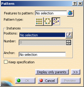
The Pattern dialog box is displayed. -
Click the User Pattern icon
 to access the
parameters specific to this type of pattern.
-
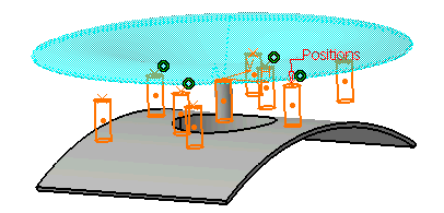
Select Rod as the feature to pattern and PatternSketch from PartBody as the Positions sketch.

-
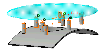
Click the orange dot located at the center of the key instance (Rod) to remove it from the pattern and click Preview.

Keep Specifications Option
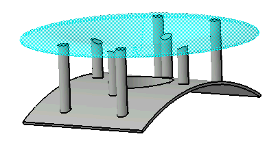
Checking the Keep specification option creates instances where a limit (To Plane/Surface, To Shell, Extend across removed faces, Trim to Shell) defined for the original feature is used for each instance. In the example below, the limit defined for the prism, i.e. the To Plane/Surface limit, applies to all instances. As the limiting surface is not planar, the instances have different lengths.
-
Turn the toggle for Keep Specification option on and click OK.
