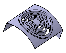
This task shows you how to create a grill.
-
Click the Grill icon
 .
.
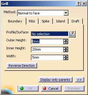
The Grill dialog box is displayed. Pictures in each tab of the dialog box help you define your parameters.
-
Keep the default method for creating the grid: the Normal to face option creates grill faces by offsetting the outer shell face.
The other method Sweep face creates grill faces by translating the outer shell face.
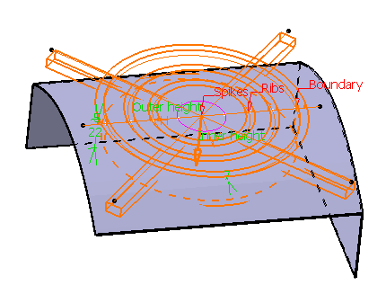
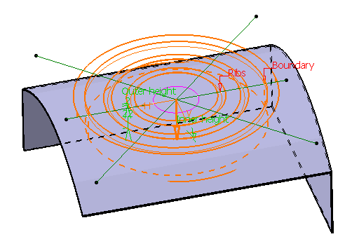
Boundary
-
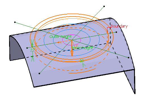
Select Sketch.4 as the boundary profile. The boundary sketch should be closed, and should lie on or outside the body.
If the profile does not yet exist, clicking the Sketcher icon enables you to sketch the profile you need.
If you are not satisfied with the profile you selected, note that you can:
-
click the Profile/Surface field again and select another sketch.
-
use any of these creation contextual commands available from the Profile/Surface field:
-
Go to profile definition. See Using the Sub-elements of a sketch.
-
Create Sketch: launches the Sketcher after selecting any plane, and lets you sketch the profile you need as explained in the Sketcher User's Guide.
-
Create Join: joins surfaces or curves. See Joining Surfaces or Curves.
-
Create Extract: generates separate elements from non-connex sub-elements. See Extracting Geometry.
-
-
-
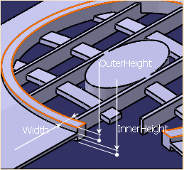
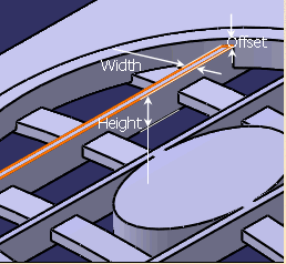
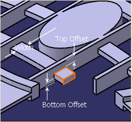
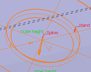
In the Outer Height field, enter 5mm to define the height of the grill outside the shellable feature. Outer Height allows the grill geometry to protrude outside of the volume. In the final feature (not the quick preview), this is measured from the outside face of the shell body.
-
In the Inner Height field, enter 22mm to define the height of the grill inside of the shellable feature. In the final feature (not the quick preview) this is measured from the outside face of the shell body.
-
In the Width field, enter 10mm to define the width of the boundary.
-
Click the Reverse Direction button to reverse the arrow. The arrow should point toward the body.
Another way of reversing the direction is by clicking the arrow.
Ribs
-
Select Sketch.3 as the ribs profile.
If no profile is defined, clicking the Sketcher
icon enables you to sketch the profile you need. -
In the Offset field, enter 2mm, to indicate that the top of the rib geometry should be 2mm below the top of the boundary geometry.
-
In the Height field, enter 22mm to define the height of the ribs.
-
In the Width field, enter 7mm to define the width of the ribs.
-
Click the Spike tab. Spike geometry is optional and is typically similar to rib geometry. The top and bottom surfaces of the spikes are defined via offsets from the top and bottoms surfaces of the ribs.
-
Select Sketch.5 as the profile defining the spikes.
-
In the Top Offset field, enter 7mm, to indicate that the top of the spike geometry should be 7mm below the top of the rib geometry.
-
In the Bottom Offset field, enter 7mm to indicate that the bottom of the spike geometry should be 7mm above the top of the rib geometry.
-
Enter 14mm in the Width field to define the width of the spikes.
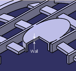
Island
-
Click the Island tab. The optional island sketch should be closed. The top and bottom of the island will match that of the rib geometry.
-
Select Sketch.2 as the island profile.
 |
Spike
|
-
To define the island wall thickness, you can set one of the two options available from the Type drop down list:
-
Use body thickness: the island wall thickness is taken from the bodies shell properties feature.
-
Enter thickness: simply enter the value you want. After this option is selected, the value field becomes available. A value of zero will be interpreted as "no walls", ie solid geometry will be produced.
-
-
Chose the Enter thickness option and enter 3mm in the Thickness value field.
Draft
-
If you wish to define a draft angle, just click the Draft tab, then set the Draft behavior option to Intrinsic to feature.
-
Just enter the desired value in the Angle field now displayed.
Click OK to confirm and create the grill. Grill.X is added to the specification tree in the Solid Functional Set.X node.
Outside
Inside