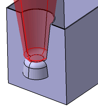
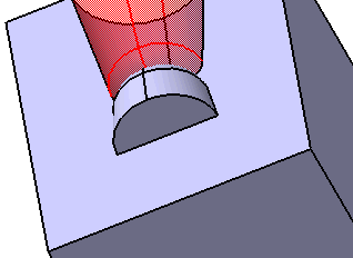
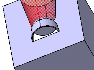
The Rest command removes material from the active body to create a platform-like area.
The area of the rest is an inner protected volume, which means that no other volumes within the same body can penetrate this area. You can add a rest to a shelled or unshelled body. The results will vary, depending on the volume type that you select. If you add a rest to a shelled body, it creates supporting walls, if necessary.
This task shows you how to create a rest.
-
Click the Rest icon
 .
.
The Rest dialog box is displayed.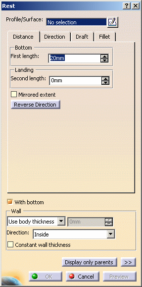
-
Select Sketch.2 as the closed profile. If no profile is defined, clicking the Sketcher
 icon enables you to sketch the profile you need.
A rest requires a closed profile on the body indicating where the rest is to be created.
If you are not satisfied with the profile you selected, note that you can:
-
click the Profile/Surface field again and select another sketch.
-
use any of these creation contextual commands available from the Profile/Surface field:
-
Go to profile definition. See Using the Sub-elements of a sketch.
-
Create Sketch: launches the Sketcher after selecting any plane, and lets you sketch the profile you need as explained in the Sketcher User's Guide.
-
Create Join: joins surfaces or curves. See Joining Surfaces or Curves.
-
Create Extract: generates separate elements from non-connex sub-elements. See Extracting Geometry.
-
Distance
-
-
Enter 8mm in the First length field to define the distance from the sketch plane up to the bottom.
-
To define the landing, enter 10mm in the Second length field to define the distance from the sketch plane up to the landing. Previewing the feature lets you get an idea of what the rest looks like. As a protected area, it is displayed in red:
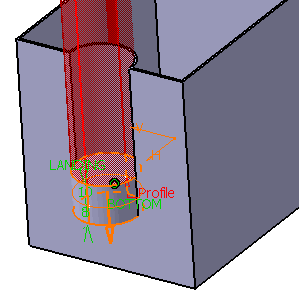
Checking the Mirrored extent option extrudes the profile in the opposite direction using the same length value as the one defined for the first length.
Clicking the Reverse Direction button reverses the extrusion direction. Another way of reversing the direction is by clicking the arrow in the geometry area.
Direction
By default, the Normal to profile option is checked, meaning that the profile is extruded normal to the sketch plane. If you wish to specify another direction, just uncheck the option, and then select a geometrical element to be used as the new reference. For the purposes of our scenario, keep the default option. Clicking the Reverse Direction button reverses the extrusion direction.
Draft
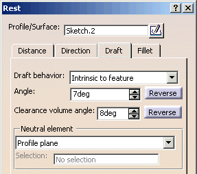
If you wish to define a draft angle, just click the Draft tab and select Intrinsic to feature in Draft behavior field. And enter the desired value in the Angle field.
The default neutral element (defines a neutral curve on which the drafted face will lie) is the Profile plane. The other possible neutral elements can be:
- Bottom
- Landing
- Plane/Surface
A Clearance volume angle and associated reverse button allows the clearance draft to be independent of the platform draft. This allows, for example, the platform draft to be used for aesthetic reasons (large draft value) and the clearance draft to be used for manufacturability (small draft value).
-
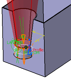
Click Draft tab and select Intrinsic to feature in Draft behavior. Enter 7deg for Angle and 8deg for Clearance volume angle. And select Reverse button at Angle.
Fillet
Checking the Lateral radius option enables you to fillet lateral edges. Then, you merely need to set the radius value of your choice.
Checking the Bottom radius option enables you to fillet bottom edges.
-
Click Fillet tab. Check the Landing radius option to fillet landing edges and enter 6mm as the radius value.
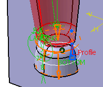
If the rest is to be shelled, you can check the Constant wall thickness option which propagates the fillets into the shell, thus maintaining a constant wall thickness.
Wall
To define the wall, you can set one of the two options available from the Type drop down list:
