 |
This task shows you how to display a
tolerancing capture .
See Managing Capture Options. |
 |
Display a tolerancing capture means show
annotations and/or annotations plane according to a specific context.
For this, during the capture edition or when a capture is set current, user
can record which elements is show/no show in the capture, see
Managing Tolerancing Capture Options.
Furthermore, user can specify a capture point of view by associating a
camera, see Creating a Tolerancing Capture.
As the capture annotation is considered as an annotation, its 3D
representation, and automatically its object in the specification tree, can
be displayed in the other captures, but take care this means that only the
capture annotation is taken into account, not the capture display. |
 |
Open the
Annotations_Part_05.CATPart document. |
|
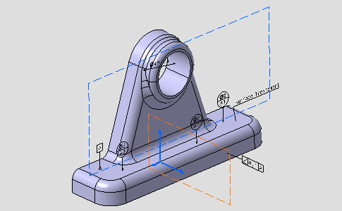
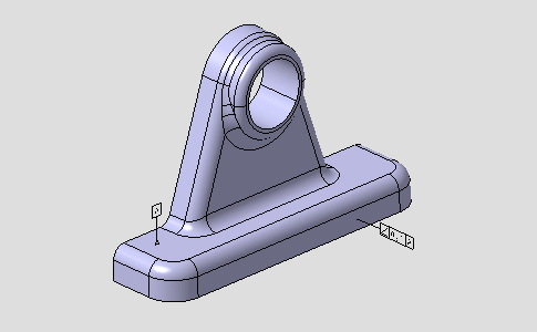
The geometry looks like this:
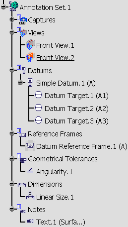
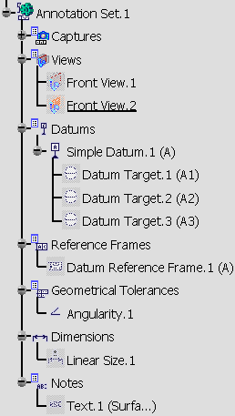
The specification tree looks like this:
 |
 |
-
Right-click the All Texts in the Captures
node and select
Display Capture command from the contextual menu.
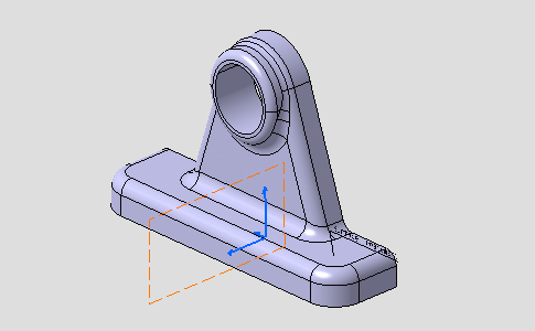
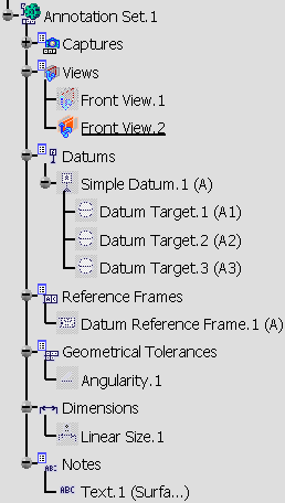
The geometry and
specification tree look like this:
- The geometry is zoomed and rotated.
- All annotations are hidden except notes.
- Front View.1 is hidden.
|
 |
 |
-
Right-click the Angularity in the Captures
node and select Display Capture form the contextual menu.
The geometry and specification tree look like this:
- The geometry is moved and rotated.
- Annotation planes are hidden.
- Only the datum and the geometrical tolerance are shown.
|
 |
 |
-
Right-click the Normal
View in the Captures node and select Display Capture form the contextual menu.
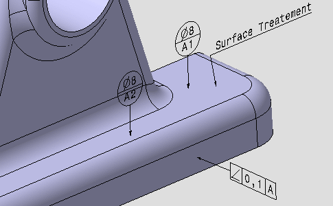
The geometry looks like this:
- The geometry is zoomed.
- Annotation planes are hidden.
- Annotations are shown.
|
 |
-
Right-click the Reverse View in the
Captures node and
select Display Capture form the contextual menu.
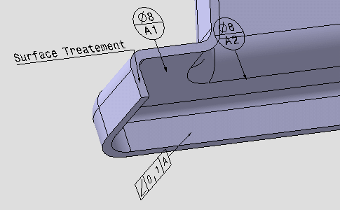
This capture has been created from the Normal View
capture and only the part orientation has been modified.
Normal View and Reverse View displays show you
that annotations are automatically mirrored. |
 |
|
 |
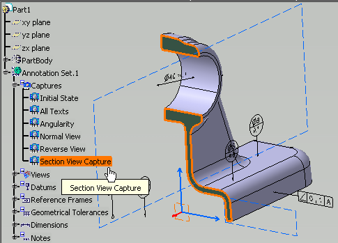
3D Preview of capture
|
|
|
 |
|
 |
-
-
-
-
-
-
|


