For a better visualization of the captures a 3D representation of the capture and/or a hidden text can be defined at the capture definition.
You can, for instance, create capture for:
- Functional part area.
- Specifications answering to given functional requirements.
- 2D view equivalent.
- 2D sheet equivalent.
- etc.
-
Click Capture
 in the Capture
toolbar.
in the Capture
toolbar.The Capture Definition dialog box appears. 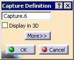
-
Click the More>> button.
The Capture Definition dialog box is expanded. 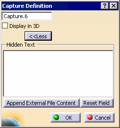
The Capture Definition dialog box displays the following information: - The capture feature name.
- Display in 3D: displays the capture in the geometry window.
- Hidden Text: displays a text as tooltip when
passing over the capture feature in the specification tree or
geometry window.
You can leave the field blank. - Append External File Content: imports from a text file the hidden text content.
- Reset Field: empties the hidden text content.
-
Select the Display in 3D option.
-
Type in the Hidden Text field the following text: This is the capture hidden text
-
Click OK in the Capture Definition dialog box.

You are now in the Tolerancing Capture workshop. - The Capture.6
is created and displayed in the specification tree and geometry window.
The name of the capture and a rectangle framing the middle characters of this name appear in the graphic area, and they form the capture callout. When you rotate the part, the capture callout remains parallel to the screen. - The hidden text is displayed when passing over the capture feature.
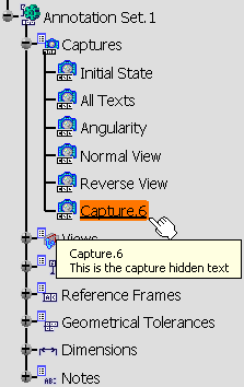
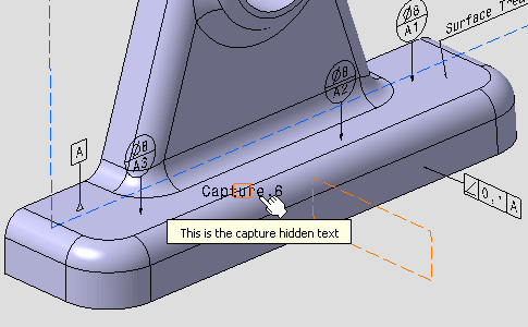
- The text of a capture callout is not editable, but follows the modifications of the capture name.
- The capture properties enable you to customize the display of the capture callout.
- The Position And Orientation toolbar
applies to capture callouts:
- for capture callouts with an associated camera:
- The X,Y manipulation applies to the text of the callout,
- The Z manipulation applies to the text and the pyramid of the capture callout.
- for capture callouts with no associated camera:
- The X,Y manipulation applies to the text and the frame of the callout,
- The Z manipulation is not relevant.
- for capture callouts with an associated camera:
- The capture callout is not linked to any annotation plane.
- The capture callout orientation is fully controlled by the 3D point of view attached to the capture.
- If you change a camera associated to a capture callout, the previous capture callout is deleted and a new one is created.
- If you remove a camera associated to a capture, the capture callout remains unchanged, the information No camera is displayed in the camera list.
- The Capture.6
is created and displayed in the specification tree and geometry window.
-
Move and rotate the part like this.
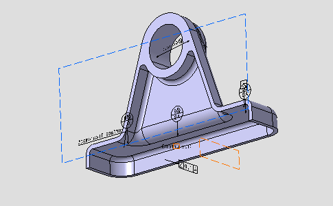
-

Create a camera is also available for any workbenches from the View > Named Views... menu. -
Click Add in the Named Views dialog box which appears.
- The Camera 1 is created.
- The part location and zoom are recorded in the camera
properties.
Click the Properties button in the Named Views dialog box to edit these properties.
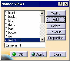
-
Select Camera 1 in the combo list of the Capture Options toolbar.

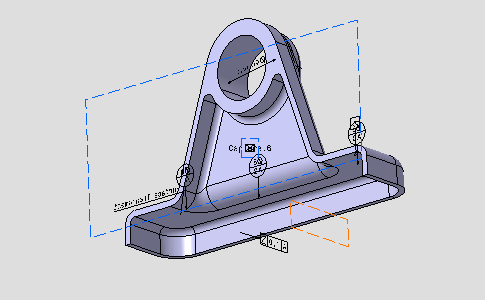
- Camera 1 is now associated with Capture.6.
- The flat rectangle framing the name of the capture is
replaced by a rectangular-based pyramid that represents the 3D view point,
see:
- When the capture is activated, the apex is displayed at the center of the screen and the base of the pyramid is parallel to the screen
- The name of the capture can be moved and a leader can be added.
-

You are back in the Functional Tolerancing and Annotations workbench. 
To edit a capture, double-click the capture in the specification tree, or the geometry window when it is displayed. 
We enter the Tolerancing Capture workshop, for editing the capture. When exiting Capture Edition, all the modifications (Show/NoShow status of the annotations, active view, camera, clipping plane, etc.) are kept i.e. visual status of the CATPart is the same as capture edition.
To get back to the previous state, user should create a specific capture before and recall it just after exiting the capture workshop.
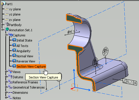
3D Preview of capture
|
|
 |