This task deals:
Creating Curvilinear Dimensions
-
Click the Curvilinear Dimensions icon:
 in the Annotations
toolbar.
-
Select a curve or an edge as shown below.
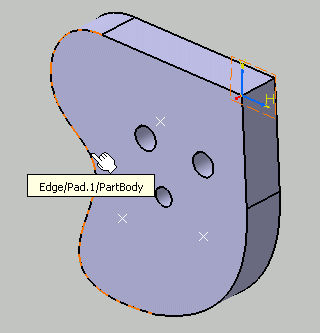
The dimension is previewed. By default, the dimension line is linear. 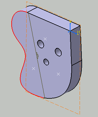
-
Right-click to display the contextual menu.
-
Select a representation mode for the dimension line:
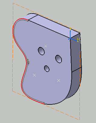
- Offset displays the dimension line as an offset curve of the projection of the measured curve.
- Parallel displays the dimension line as a parallel curve of the projection of the measured curve.
- Linear displays the dimension line as a straight line, parallel to the direction defined by the limit points of the measured curve.
Select Offset for example. The dimension line is modified accordingly.
-
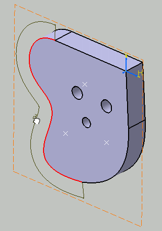
Optionally drag the dimension line and/or the dimension value to position them as wanted.
-
Click in the free space to validate and end the dimension creation. The semi-arc symbol displayed over the dimension value symbolizes a curvilinear length dimension. You can now handle the dimension just like any other dimension.
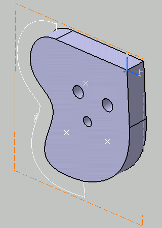
- With an Electrical Harness Installation license, you can also select starting and ending points, planar faces or splines, which lets you define the total length of several harness routing curves.
- A curvilinear dimension is retrieved from the fake dimensions defined
in Electrical Harness Installation workbench.
You cannot modify the curvilinear dimension value in 3D Functional Tolerancing and Annotation workbench, to do this you must modify the fake dimension value in Electrical Harness Installation workbench. - For more information refer to the Electrical Harness Installation User's Guide.
Creating Curvilinear Fake Dimensions
-
Switch to the Product Functional Tolerancing and Annotation workbench.
-
Select Curvilinear Dimensions
 in the
Dimensions
toolbar.
You are prompted to select the first element for the dimension creation.
-
In the context of the Electrical Harness product, you can select a plane, a point or a spline.
-
Whatever the number of elements, at least one spline must be selected.
-
They must be ordered from one end to the other.
-
They must be in an electrical part (connector, equipment, bundle segment, support, back shell, protective covering, etc.)
-
The electrical continuity between the different elements selected is mandatory.
-
-
Select for example: a spline. Click to create the dimension. Optionally, you can drag the dimension
line and/or the dimension value to position them as wanted.
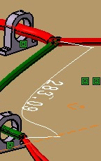
-
Right-click the dimension and in the contextual menu, choose Properties. Click the Value tab and
then select Alphanumerical to highlight the *Fake* field for Main and Dual values. Enter for example: Main : 290.
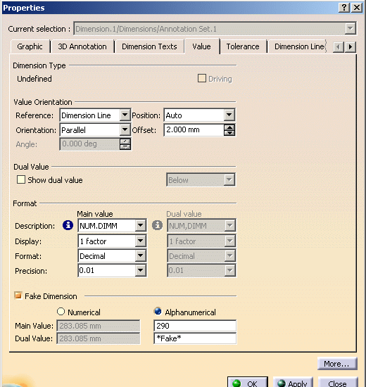
-
The new dimension value is updated in the drawing.
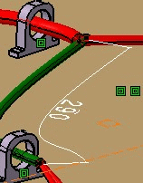
-
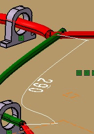
Now change the length of this spline by changing the coordinates of Point.1. For example changing X-coordinate from -200mm to -210mm of the spline in the Point definition dialog box. Click OK.
-
You can see that even though the length of spline has increased, the dimension remains the
same.
-
Right-click the dimension and in the contextual menu, choose Properties. Click the Value tab and
clear the Fake Dimension check box. Click OK. Now the modified new dimension value will be displayed.
More about curvilinear dimensions
- The curvilinear length symbol is defined in the standards.
- You cannot measure a segment of a curve.
- In some cases, depending on the curve and on the offset value, the offset representation mode cannot be computed (because the dimension line cannot intersect with itself along the curve): you will not be able to position the dimension further than a certain limit.
- You can change the dimension line representation mode after the dimension has been created.