This task shows you how to use the Select Mesh Parts button available in several dialog boxes of the Generative Structural Analysis workbench.
When a geometrical support is selected, this button allows you to choose one mesh part between all the activated or deactivated mesh parts associated to this support, and so, to apply pre-processing specifications (Restraints, Loads, Masses, Analysis Connections) to a transformed mesh part.
You have to select a support to make this button available.
Open the sample19.CATAnalysis from the sample directory. This file contains two transformed mesh parts (Translation Mesh.1 and Translation Mesh.2).
-
Double-click Pressure.1 in the specification tree (under the Loads.1 set).
-
Click the Select Mesh Parts button
 in the Pressure dialog box.
The Mesh Parts dialog box appears.
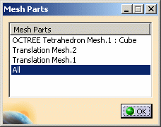
- Mesh Parts: gives you the list of all the existing
mesh parts (activated or deactivated mesh parts).
You can select the desired mesh parts.
- All: this option takes into account all the
existing mesh parts even if they are created after this
operation.
By default, the All option is selected.
- All: this option takes into account all the
existing mesh parts even if they are created after this
operation.

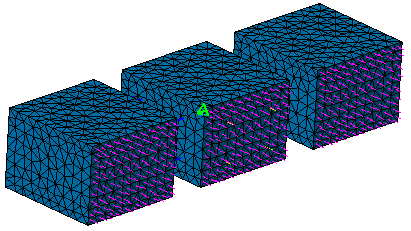
To visualize the mesh parts on which the pressure is applied, activate the Mesh.1 image (under the Nodes and Elements set) and the Pressure Vector.1 image (under the Loads.1 set), and if needed, change the visualization options of the pressure vector image.
In this particular example, the pressure is applied to all the mesh parts (the parent mesh part and the two transformed mesh parts):
- Mesh Parts: gives you the list of all the existing
mesh parts (activated or deactivated mesh parts).
You can select the desired mesh parts.
-
Select the desired mesh part.

Multi-selection of mesh parts is available.
In this particular example, select Translation Mesh.2 as mesh part.
-
Click OK in the Mesh Parts dialog box.
-
Click OK in the Pressure dialog box.
-
Click the Compute icon and select the Mesh Only option in the Compute dialog box.
-
Activate the Pressure Vector.1 image (under the Loads.1 set).
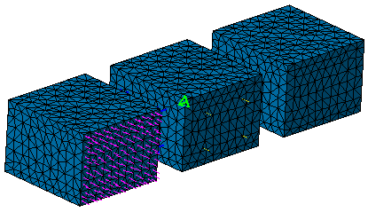
The pressure is applied only to the selected mesh part:
Pre-processing Specifications Applied to Activated/Deactivated Mesh Part
A pre-processing specification applied to a mesh part is taken into account only if it is applied to activated elements or activated nodes.
A mesh part is composed of elements and nodes, so when you activate or deactivate a mesh part, the activation status is propagated to the elements and to the nodes of this mesh part.
- An element can belong to only one mesh part, so the element has the same activation status as the mesh part (if the mesh part is deactivated, the element is also deactivated).
- A node can be shared by several elements and then by several mesh parts. A node is activated if it is linked to at least one activated element (or mesh part).
If you do not want to apply pre-processing specifications to a deactivated mesh part, make sure this mesh part does not share nodes with an activated and selected mesh part.
To know more about the activation or deactivation of mesh part, refer to Advanced Meshing Tools User's Guide - Reference Information - Activating/Deactivating Mesh Parts.
Example
Consider the following example with two surfaces:
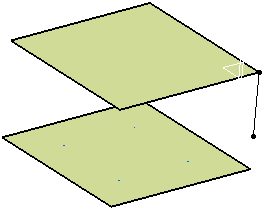
The upper surface is the support of the Advanced Surface Mesh.1 mesh part.

Note that the Advanced Surface Mesh.1 mesh part is deactivated and the Extrusion Mesh With Translation.1 mesh part is activated. To visualize the Extrusion Mesh With Translation.1 mesh part, right-click Nodes and Elements and select Mesh Visualization.
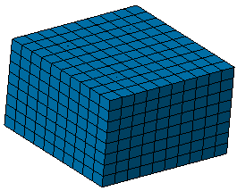
You can now deactivate the Mesh image.
-
Insert two static analysis cases.
-
In the both analysis cases, clamp the lower surface.
-
In the first static case, create a distributed force.
To do this:
-
Click Distributed Force
 in the Loads toolbar.
 -
Select the upper surface as support.
-
In the Z box, enter -100N and click OK.
-
-
Compute the first analysis case and click Von Mises Stress
 in the Image toolbar.
The Von Mises stress (nodal values).1 image is displayed:
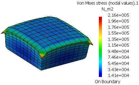
The distributed force is applied to the element nodes that are shared by the deactivated Advanced Surface Mesh.1 mesh part and the activated Extrusion Mesh With Translation.1 mesh part: the element nodes are activated and then the distributed force load is taken into account by the solver.
-
In the second static analysis case, create a force density.
To do this: -
Click Force Density
 in the Loads toolbar.
 -
Select the upper surface as support.
-
In the Z box, enter -100N and click OK.
-
-
Compute the second analysis case and click Von Mises Stress
 in the Image toolbar.
The Von Mises stress (nodal values).2 image is displayed:
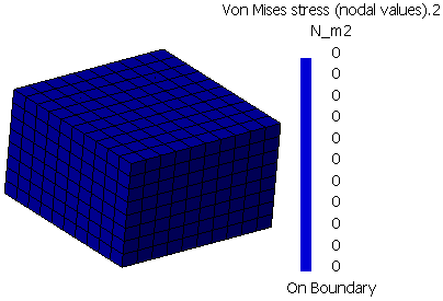
The force density is applied to the elements that belong to the deactivated Advanced Surface Mesh.1 mesh part: the elements are deactivated and then the force density load is ignored by the solver.