This task shows you how to create the equivalent of the existing line force density, surface force density and volume force density by giving only as input a force in Newton (N in SI) and not a force density (N/m in SI for a line force density, N/m2 in SI for a surface force density and N/m3 for body force).
Force Densities can be applied to the following types of supports:
|
Geometrical Feature |
Mechanical Feature |
Analysis Feature |
||||
|
Spatial Groups |
Geometrical Groups |
Groups by Neighborhood |
Groups by Boundary |
Others |
||
|
Point/Vertex (homogeneous selection) |
|
|||||
To know more, refer to Authorized Supports.
Open the sample00.CATAnalysis document from the samples directory.
-
Go to View > Render Style > Customize View and make sure the Shading, Outlines and Materials options are active in the Custom View Modes dialog box.
-
Click Force Density
 in the Loads toolbar.
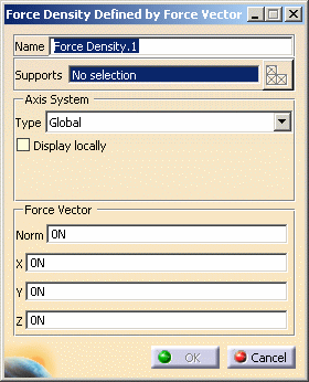
The Force Density Defined by Force Vector dialog box appears.

- Name: gives you the name of the force. If needed, you can change it.
- Support: lets you select the support.

- Multi-selection is available and must be homogeneous.
- You can select edge, surface or bodies (2D or 3D).
- Axis System:
- Type:
- Global: if you select the Global Axis system, the components of the force density field will be interpreted as relative to the fixed global rectangular coordinate system.
- User: if you select a User-defined Axis system,
the components of the force density field will be interpreted
as relative to the specified rectangular coordinate system.
To select a User-defined Axis system, you must activate an existing Axis by clicking it in the specification tree.
Its name will then be automatically displayed in the Current Axis field.
The Local orientation is Cartesian: the components of the surface traction field are interpreted as relative to a fixed rectangular coordinate system aligned with the Cartesian coordinate directions of the User-defined Axis.

- You can define the force density direction by using the compass.
- You can modify the compass orientation either with the mouse or by editing the compass.
- By applying the compass to any part geometry, you can align the compass directions with the implicit axis directions of that geometry: drag the compass by handling the red square and drop it on the appropriate surface. The normal direction to this surface defines the new direction. Then, click on the Compass Direction button to take this new direction into account. You can now invert the direction if desired, editing the values of the three components.
- Display locally: lets you display the selected axis system.
- Type:
- Force Vector: lets specify the value of the force vector component.
-
Specify the Axis System.
In this particular example, select Global as axis system Type.
-
Select the desired geometry support.
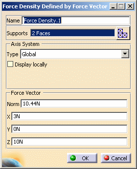
In this particular example, select the two following surfaces.

Symbols representing the force are displayed on the selected support to visualize the force density field.
As soon as the support is selected, the Select Mesh Part button is available.
To know more about the Select Mesh Part button, refer to Selecting Mesh Parts. -
Specify the desired Force Vector value.
In this particular example, enter 3N as X value and 10N as Z value.
Note that:
- The corresponding Norm value is automatically
computed and displayed.

- The visualized symbols orientation is also updated to reflect
the modification.

- The corresponding Norm value is automatically
computed and displayed.
-
Click OK.
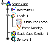
A Force Density.1 load appears in the specification tree under the Loads.1 set.

![]()