This task shows you how to create a Point Analysis Connection.
Point analysis connections are used for projecting welding points onto
parallel faces, on an assembly model.
- Only available with the Generative Assembly Structural Analysis
(GAS) product
 .
. - The connection has to connect two bodies (2D or 3D).
- Multi-selection is not available.
Open the sample48.CATAnalysis from the samples directory.
-
Click Point Analysis Connection
 in the Analysis Supports toolbar.
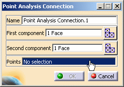
The Point Analysis Connection dialog box appears.
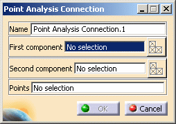
- Name: lets you change the name of the connection.
- First component: lets you select the first "side" of
the part that will support the connection.

You can select one body (2D or 3D) or one mesh part.
- Select Mesh Parts: this button is available only
if a support is selected.
For more details, refer to Selecting Mesh Parts.
- Select Mesh Parts: this button is available only
if a support is selected.
- Second Component: lets you select the second "side"
of the part that will support the connection.

You can select one body (2D or 3D) or one mesh part.
- Select Mesh Parts: this button is available only
if a support is selected.
For more details, refer to Selecting Mesh Parts.
- Select Mesh Parts: this button is available only
if a support is selected.
- Points: lets you select the welding points.

You can select an Open body containing several points.
-
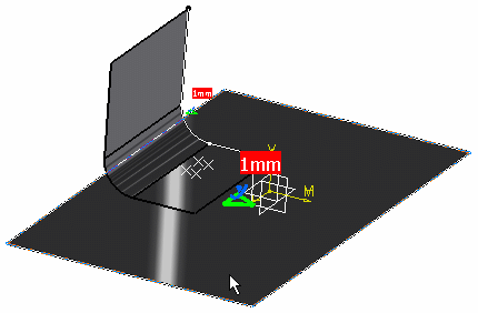
Select the first component.
In this particular example, select the Part6(Part6.1).
-
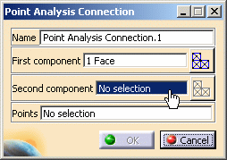
Activate the Second component field.
To do this, select the Second component edit box as shown below:
-
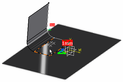
Select the second component.
In this particular example, select the Part5(Part5.1).
-
Activate the Points field.
To do this, select the Points edit box as shown below:
-
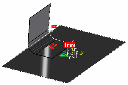
Select the welding points.
In this particular example, select the Points open body (under the Part5).
A symbol representing the point design connection appears on the assembly.
-
Click OK.
The Point Analysis Connection.1 connection appears in the specification tree under the Analysis Connection Manager.1 set.

- You can update analysis connections.
For more details, refer to Updating Analysis Connections. - You can now apply a connection property on the connection you just
have created.
For more details, refer to Creating Spot Welding Connection Property.