This task shows how to create a Spot Welding Connection between two parts.
A Spot Welding Connection is the link between two bodies, using point analysis connections or point analysis connections within one part.
Only available with the Generative Assembly Structural Analysis (GAS) product.
Open the sample48_1.CATAnalysis document from the samples directory.
-
Make sure you know all you need about what type of property you will use for what type of connection.
-
Click Spot Welding Connection Property
 in the Connection Properties toolbar.
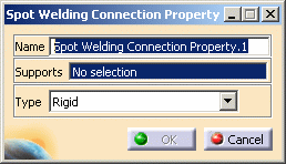
The Spot Welding Connection Property dialog box appears.
-
Name: lets you change the name of the connection property.
-
Supports: lets you select the connection you want to associate to a property.

You can apply the spot welding connection property:
-
on Point Analysis Connection and Point Analysis Connection within one Part (from R12)
-
on a joint body of the Body in White Fastening workbench
-
on Spot Welding Connection (before R12)
For more details, refer to About Connection Properties.
-
-
Type: allows you to choose between:
-
Rigid
-
Spring-Rigid-Spring
-
Rigid-Spring-Rigid
-
Beam
-
Hexahedron
-

-
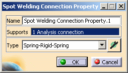
If you select the Beam, Spring-Rigid-Spring, Rigid-Spring-Rigid or Hexahedron option type, the Component edition icon appears
 .
. -
The Component edition icon can have two status:
-
valid:

-
invalid:

-
-
If you select Beam or Hexahedron option type, you can select an user-defined material.

For more details, refer Creating an User Material.
-
-
Select a spot welding connection.
In this particular example, select the Point Analysis Connection.1 in the specification tree.

-
Select the desired Type option.
In this particular example, select the Spring-Rigid-Spring option Type.
-
Click the Component edition icon
 to specify the parameters.
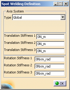
The Spot Weld Definition dialog box:
-
the Axis System Type combo box lets you to choose between Global or User Axis systems for defining the degrees of freedom directions.
-
Global: if you select the Global Axis system, the degree of freedom directions will be interpreted as relative to the fixed global rectangular coordinate system.
-
User: if you select a User Axis system, the degree of freedom directions will be relative to the specified Axis system. Their interpretation will further depend on your Axis System Type choice.
To select a User Axis system, you must activate an existing Axis by clicking it in the features tree. Its name will then be automatically displayed in the Current Axis field.
If you select the User Axis system, the Local orientation combo box further allows you to choose between Cartesian, Cylindrical and Spherical Local Axis Orientations.
-
- Translation and Rotation stiffness
values.
-
Translation stiffness 1 = Translation in X
-
Translation stiffness 2 = Translation in Y
-
Translation stiffness 3 = Translation in Z
-
Rotation stiffness 1 = Rotation in X
-
Rotation stiffness 2 = Rotation in Y
-
Rotation stiffness 3 = Rotation in Z
-
-
-
Modify the desired parameters in the Spot Weld Definition dialog box.
-
Click OK in the Spot Weld Definition dialog box.
-
Click OK in the Spot Welding Connection dialog box.
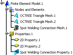
A Spot Welding Connection Property.1 connection property appears in the specification tree under the Properties.1 set and a Spot Welding Connection Mesh.1 connection mesh part appears under the Nodes and Elements set.
-
You can edit the Weld Spot Connection Mesh.1 object.
To do this, double-click the Spot Welding Connection Mesh.1 object in the specification tree.
The Spot Welding Connection Mesh dialog box appears.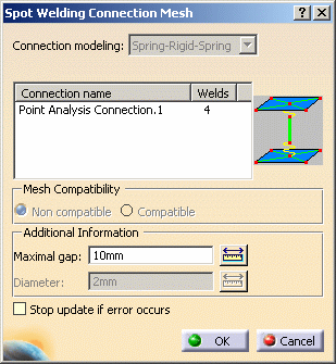
For more details about the weld spot connection mesh parts, refer to Meshing Spot Weld Connections in the Advanced Meshing Tools User's Guide.
-
You can visualize the connection mesh.
To do this:-
Compute the mesh only (for more details, refer to Computing Objects Sets).
-
Generate a Mesh image (for more details, refer to Generating Images).
-
![]()