Only available with the ELFINI Structural Analysis (EST) product.
Multi load sensors are only available in a static analysis case containing a multi load set.
Open the sample46.CATAnalysis document from the samples directory.
-
Perform a mesh only computation.
To do this, click Compute and select Mesh Only from the list.
-
Right-click the Sensors.3 set in the specification tree and select Create Resultant Sensor > Multi Load Sensor
 .
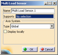
.The Multi Load Sensor dialog box appears.

-
Name: lets you modify the name of sensor you create.
-
Supports: lets you select the support.
-
Non homogeneous multi selection is available.
The support can be a:-
Geometry (point, edge, face)
-
Mechanical feature (part body, joint, ...)
-
Group (geometrical, by proximity, by boundary).
-
-
The support selection is not mandatory. If you do not select any support, then the whole geometry is taken into account: the resultant will be the global resultant of the entire multi load set.
-
-
Supports: lets you select or not a support.
If you do not specify a support, all the part body will be selected by default.
Non homogeneous multi selection is available.
The support can be a:-
Geometry (point, edge, face)
-
Mechanical feature (part body, joint, ...)
-
Group (geometrical, by proximity, by boundary).
-
-
Axis System: lets you choose the type of axis in which the multi sensor will be computed and displayed in the 3D view.
To know more about the axis system, refer to Axis System Type.
-
-
Select the desired Supports.
In this particular case, do not select a support.
By default, all the body will be taken into account. -
Select the desired Axis System.
In this particular case, select Global.
-
Select the Display locally check box.
-
Click OK.
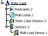
The Multi Load Sensor.1 sensor appears in the specification tree.

Note that the multi load sensor is not updated.
To see the values of the multi load sensor, you have to generate a report.
To do this: -
Update the sensor set.
To do this, refer to Updating Sensors.
-
Right-click Sensors.3 and select Report.
To know more about the Report contextual menu, refer to Generating Reports.
An html report is displayed. This file contains the value of the multi load sensor you created.
You can update a sensor (you just have created or modified) or you can update all the sensors belonging to a sensor set.
![]()