This task shows how to visualize the mesh without deformation.
Open the sample21.CATAnalysis document from the samples directory.
-
Right-click Nodes and Elements in the specification tree and select Mesh Visualization
 .
.The Mesh.1 image appears in the specification tree under the Nodes and Elements set.
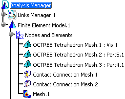
The image is also visualized:
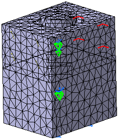
-
Double-click Mesh.1 in the specification tree to edit it.
The Image Edition dialog box appears.
To know more, refer to Image Edition. -
Select the Selections tab.
-
Double-click Contact Connection Mesh.1 in the Available Groups list.
The mesh visualization is filtered: only the selected connection mesh part is displayed.
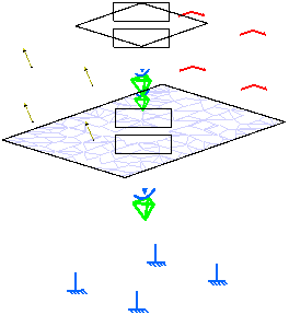
-
Double-click OCTREE Tetrahedron Mesh.1: Vis.1 in the Available Groups list.
Both the Contact Connection Mesh.1 and OCTREE Tetrahedron Mesh.1: Vis.1 mesh parts are displayed.
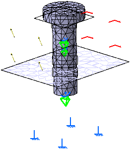

For a better visualization, you can hide one by one all the mesh parts, the Properties.1 set, the Restraints.1 set and the Loads.2 set.
To do this, right-click the entity you want to hide in the specification tree and select Show/Hide.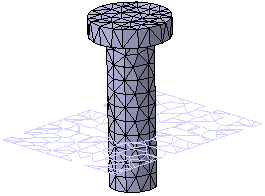
-
Click OK in the Image Edition dialog box.
The image corresponding to the settings you defined is now visualized.
With the ELFINI Structural Analysis product you can generate reports
of the deformed mesh image.
To know more, refer to Generating
Reports.
![]()