This task shows you how to insert a solution case.
Solution case is a new type of Analysis Case gathering a collection of solutions (assembled solution or imported solution).
Once a solution case is created, you can add an assembled solution and you can import an exported solution.
You will see how to:
You will also find a recommended methodology to use the transfer of displacements.
Open the sample14_1.CATAnalysis document from the samples directory.
Inserting a Solution Case
Only available with the ELFINI Structural Analysis (EST)
product
![]() or the Generative Assembly Structural Analysis (GAS) product
or the Generative Assembly Structural Analysis (GAS) product
![]() .
.
-
Select Insert > Solution Case
 .
.An empty Solution Case.1 feature appears in the specification tree.
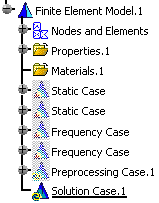
You can now access the Add Solution contextual menu:
-
Assembled Solution...: lets you select solutions belonging to sub analyses.
-
Imported Solution: lets you import solutions that have been previously exported.
-
Adding Assembled Solution
Assembled solution (also called displacement assembly) is created in an assembled analysis. This solution is the concatenation of several solutions computed in sub analyses.
The aim of displacement assembly is to post-process all the component of an assembled model:
- without building a formal assembled analysis (for example: without connection and preprocessing specification). Only the component positioning is required.
- without computing the assembly level (based on computations made at sub analysis level).
In the case of a plane analysis, the displacement assembly allows you to make fast comparison between two sections of the plane (by generating images, enveloping, ...).
You can add several assembled solutions in the same solution case.
Only available with the Generative Assembly Structural Analysis (GAS) product.
-
Right-click Solution Case.1 and select Add Solution > Assembled Solution
 .
.An Assembled Solution.1 object appears under Solution Case.1 in the specification feature.

You now have to define the assembled solution.
To do this: -
Double-click Assembled Solution.1 in the specification tree.
The Assembled Solution dialog box appears.
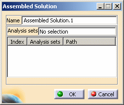
- Name: lets you change the name of the assembled solution.
-
Analysis Sets: lets you select the solution you want to assemble.

- You can select only the solutions belonging to sub analyses.
- You cannot select solutions belonging to the assembled analysis.
- You cannot assemble:
- Mono occurrence solutions and multi occurrences solutions
- Multi occurrences solutions that have not the same number of occurrences (a message will appear while launching a computation).

To select a solution, you can:
- Select it directly in the specification tree
- Use the Edit > Search... menu.
- Index: gives you the identification number of the selected analysis solution.
- Analysis Sets: gives you the name of the selected analysis solution.
- Path: gives you the path of the
selected solutions.
You can hide or show the path of the selected solution using the Show Path contextual menu.
-
Select the solution you want to assemble.
In this particular example, select:
- Static Case Solution.1 under Surface1 (Surface1.1)
- Static Case Solution.1 under Surface2 (Surface2.1).

You can also use the Search functionality.
To do this:-
Select Edit > Search... (or press Ctrl+F).
The Search dialog box appears.
-
Enter *solution* in the Name field of the General tab.
-
Click Search
 .
. -
Select the desired lines in the found objects list and click Select.
-
Click Close.
The Assembled Solution dialog box is updated:
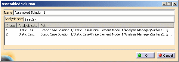
If you select a line and then you right-click it you access the following contextual menus:
- Delete: lets you delete the selected line from the list.
- Delete All: lets you delete all the content of the list.
- Show Path: lets you hide or show the path of the selected analysis solution.
-
Click OK.
-
Compute the solution.
To do this:
-
Select Assembled Solution.1 in the specification tree.
-
Click Compute
 .
. -
Click OK.
Then you can generate images.
To do this, right-click Assembled Solution.1 and select Generate Images. -
-
Generate images.
To do this:
-
Right-click Assembled Solution.1 in the specification tree.
-
Select Generate Image.
-
Select the images you want to generate.
-
Click OK.
-
The results of assembled solutions are not kept when you save and close the .CATAnalysis file, but you can generate them by launching a computation or activating an image.
Adding Imported Solution
The import of solution lets you transfer displacements.
A transfer of displacements is a copy as results of solutions, between a
source document and a target document based on identical meshes.
The displacement import is the second step of the displacement transfer between a document to another.
You can add several imported solutions in the same solution case.
- The source document and target document must be based on identical meshes.
- If you exported a solution from a model containing thermal loading (and therefore an environment set), only displacements will be taken into account during the import execution. Since thermal information are not saved into the CATAnalysisExport file, resulting stress distribution will not take into account thermal effects.
Only available with the ELFINI Structural Analysis (EST) product.
-
Right-click Solution Case Solution.1 and select Add Solution > Imported Solution
 .
.The Imported Solution dialog box appears.
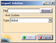
-
File:
-
Browse: lets you select the desired file (a .CATAnalysisExport file).
-
-
Axis System: lets you define the axis system in which the imported displacements will be taken into account.
To know more about the axis system management in the import context, refer to Axis System Management.
To know more about the selection of an axis system, refer to Axis System Type.
-
-
Click Browse and select the desired .CATAnalysisExport file.
To know how to export solution and then generate a .CATAnalysisExport file, refer to Exporting Solutions.
-
Choose the Axis System type.
In this particular example, select Global.
-
Click OK.
The Static Case Solution.1 feature appears in the specification tree.


The name of the imported solution is given by the name of the solution that has been exported.
For example, if you export three static solutions (Static Case Solutions.1, Static Case Solutions.2, Static Case Solutions.4), the result of the import will be:
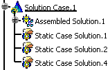
You can generate images.
To do this, right-click Static Case Solution.1 and select Generate Images.
![]()
More About Transfer of Displacements
You will find here the recommended methodology to use the transfer of displacements.
You can use the transfer functionality to perform the two following scenarios.
Transfer from an Assembly to Sub Analysis
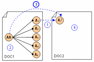
-
You make a copy of the sub analysis A1.
-
You compute displacements at the assembly level (AA).
-
You export local displacements from assembled analysis and import them in the copy of the sub analysis.
-
You can generate images.
Transfer between Two Analyses Based on Identical Mesh
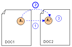
-
You make a copy of the analysis A1.
-
You export local displacements from assembled analysis and import them in the copy of the analysis.
-
You can generate images.
Axis System Management
You can select an axis system
-
Transfer of displacements from an assembly of analysis to a sub-analysis:
The displacements exported on file will be expressed in the local axis of the sub analysis.
Consequently, if the file is imported in a copy of the sub analysis, there will be no need to specify a user axis.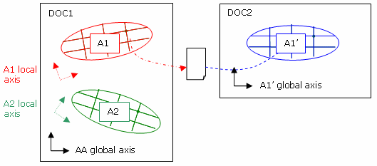
-
Transfer from an analysis to another:
The displacements exported on file will be expressed in the global axis of the analysis.
Consequently:-
If both analyses have the same position, the import must be done in the global axis.

-
If they have not the same position, the import must be done in a user axis reflecting the transformation.

-
Synchronization Mechanism
There is no synchronization mechanism.
If a CATAnalysisExport file already imported is re-generated
from a modified solution and then re-imported in the same Solution Case,
then a new solution set will be added under the Solution Case.
Update Mechanism
If the imported solutions are invalidated (for example,
after a mesh modification), you cannot update these solutions. The only way
is to re-import the CATAnalysisExport file using the the
Add Solution > Imported Solution functionality.
Open the sample14_1.CATAnalysis document from the samples directory.
-
Compute all the solutions.
To do this, refer to Computing Object Sets.
-
Right-click Static Solution.1 and select Export > Solution.
-
Click Browse, select the directory in which you want to save the .CATAnalysisExport file and enter a file name.
-
Click Save.
-
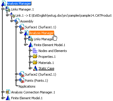
Select Analysis Manager (under Surface1) as Selected Sub Analysis.
-
Click OK.
-
Right-click Analysis Manager (under Surface1) in the specification tree and select Analysis Manager Object > Open in New Window.
The AnalysisSurface11.CATAnalysis appears in a new window.
-
Select Insert > Solution Case.
-
Right-click Solution Case.1 and select Add Solution > Imported Solution.
-
Click Browse and select the .CATAnalysisExport file you generated.
-
Click OK.
You can now generate images.
![]()