This functionality is available in Electrical Part Design workbench only.
A support is a mechanical object used to hold the bundle segments in position.
-
Click Define Support Part
 .
.
You are prompted to select a part. -
Select the support either in the specification tree or in the geometry area.
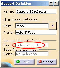
The Support Definition dialog box opens: 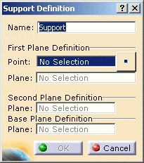

-
Enter/change the name for the support.
-
Select the point through the support, to define the reference position of the bundle segment in the support.
Note: Using the Define Support Part command several times on the same support allows you to define several ways through (multi-support). 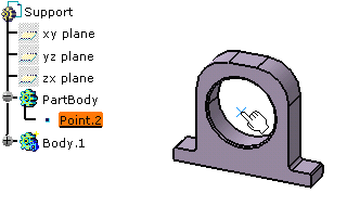
If the point is not already defined, click the  button.
For more information, refer to the Point Definition.You are prompted to select the first plane: the way in of the support. -
Select the front face.
You are prompted to select a second plane: the way out of the support. -
Select the opposite face.
To be selectable, it must be parallel to the first face. -
Optionally, select a base plane to define a retainer. Refer to Creating Retainers.
If nothing is selected, the support is considered as standard one. -
Click OK to validate.
The specification tree is updated: Two extra planes have been defined (Plane.1 and Plane.2) and publications created.
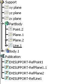
- When you define another way through a support (multi-support), the
second plane is predefined as it is for the first way.
A first way through the support has been created: 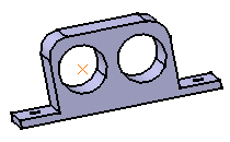
Using the previous steps, when you select the support a second time to create the second way through: - Select another point
(or define one if necessary by clicking the button).
 - The second plane is already defined.
- Select another point
- Defining supports generates Publication labels: if you instantiate the support in a product environment, it can be replaced, keeping the links with the bundle segments going through the support.
- The Base Plane Definition field is used for the retainer type of support.
