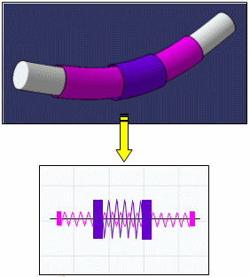
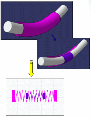
You can create your own line type standard for protective coverings that gives a different aspect to these components in your drawing and lets you better visualize the various overlapping coverings. This functionality is only available when generating drawings using generative view style parameters.
For each basic line type, you must define more than one bi-dimensional line type, increasing its size as you go in order to obtain one linetype per layer of protective covering.
When generating your drawing, the system maps the appropriate line type to each layer of protective covering using a simple formula.
The above illustrations also show 2D details applied to the ends of protective coverings that likewise vary in size according to the covering layer. For more information, see Integrating Generative View Styles.
Also refer to Using Different Line Types and 2D Details for Overlapping Protective Coverings.
![]()
The aim of this task is to create your own line type standard for protective coverings.
-
You must run a CATIA session in administrator mode. To do so, refer to Locking Settings in the
CATIA Installation and
Administration User's Guide (Administering Version 5 section,
Managing Settings chapter). -
Have specified the location of customized standards by setting the CATCollectionStandard variable.
To learn more about the CATCollectionStandard variable, see About Standards.
You will find useful information from step 6 onwards.
-
Select the Tools > Standards... menu item.
The Standard Definition dialog box pops up. -
In the Category list box, select drafting. And in the File list box, select ANSI.xml.
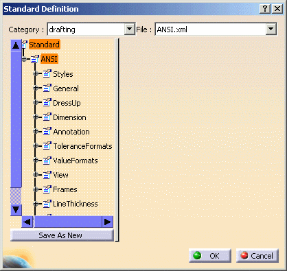
The Save As New command is now available.
-
Select LineTypes in the left-hand list:
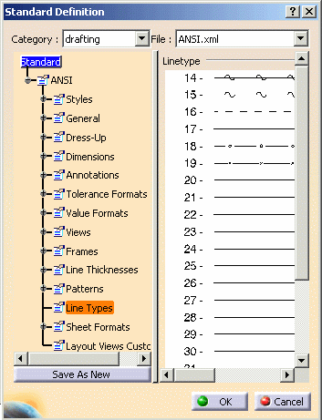
-
Click Save As New and save the document with another name in the folder you specified by the CATCollectionStandard variable:
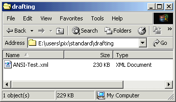
This way you can customize more than one line type standard, that for example, will allow you to produce drawings having different line types for different customers. -
Then double-click a line in the list and modify its aspect.
Define more than one bi-dimensional line type per basic line type you want to create, increasing its size as you go so that you will obtain one linetype per layer of protective covering.
Your document is updated. 
When creating protective coverings, line types offered in the Line type list are taken from the Tools > Options > General > Display > Linetype tab. To map line types in the standard you have just created to those in the Tools > Options dialog box, you must update the list in the Linetype tab.
-
To update line types in the Linetype tab, select the Tools > Options menu item.
The Options dialog box displays:

-
Select the General > Display > Linetype tab:
-
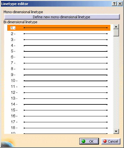
Double-click one of the line types you created in the steps above.
The Linetype editor dialog box opens:
-
Select the corresponding line type number previously created and click OK to validate.
The list in the Options dialog box is updated. -
Repeat for other line types.
-
Click OK to validate the changes in the Options dialog box.
You can now use this line type standard for your drawings.
For more information, see:
- Interactive Drafting User's Guide - User's Tasks - Administration Tasks - Administering Standards and Generative View Styles
- Interactive Drafting User's Guide - User's Tasks - Administration Tasks - Setting Standard Parameters and Styles - Setting Standard Parameters - Linetype Definition