The second part of this section shows a basic example of how standards impact the documents you create.
Introduction
Standards can be customized afterwards according to your needs but bear in mind that unless you are logged as administrator, you will not able to modify standards.
There are two types of standards:
- default standards provided by Dassault Systèmes.
These standards can be customized using the interactive standard editor.
For detailed information on each type of standards, you have to refer to the corresponding documentation. These default standards are dispatched in several categories:- General parameters including
- default graphic attributes (for Solids, OpenBodies, Points, Lines, Planes and Surfaces) in CATStdMechanicalDesign.xml
- attributes for layers and filters in
- CATStdLayerAndFilter.xml and CATStdTypeLayerAndFilter.xml for CATPart documents
- CATDftStdLayerAndFilter.xml and CATDftStdTypeLayerAndFilter.xml for .CATDrawing documents.
Refer to Customizing Standards for Layers and Filters in this guide.
- attributes for line thickness in CATStdLineThickness.xml.
Note that these attributes are relevant for .CATDrawing documents
only.
Refer to Customizing Standards for Line Thickness in this guide - Aerospace SheetMetal Design parameters in AerospaceSheetMetalDesign.xml. For detailed information, refer to the Version 5 - Aerospace SheetMetal Design User's Guide - "Administration Tasks".
- Drafting parameters: as far as .CATDrawing documents are concerned, the use and administration of their specific standards (dress-up, annotations, etc.) is detailed in the Version 5 - Interactive Drafting User's Guide - "Administration Tasks"
- DXF/DWG Interface parameters: for detailed information, refer to the Version 5 - Data Exchange Interfaces User's Guide - "Administration Tasks".
- Generative parameters: for detailed information on generative view styles, refer to the Version 5 - Generative Drafting User's Guide - "Administration Tasks".
- General parameters including
As far as default standards are concerned, their file name cannot be modified.
- user standards which are created and managed by the administrator.
Standard files are identified by two runtime environment variables which are:
For detailed information on environment variables, refer to
What is An
Environment? in the Version 5 Installation and Administration Guide.
For detailed information on how to set variables, refer to
Customizing
Your Environment on Window or
Customizing
Your Environment on UNIX (depending on your operating system).
Impact of standards - Example
- Access the following folder to copy the CATStdMechanicalDesign file:
C:\Program Files\Dassault Systemes\Bn\intel_a\startup\templates(where
nis the current release number) - Paste the CATStdMechanicalDesign file in the following
folder:
C:\Program Files\Dassault Systemes\Bn\intel_a\resources\standard
![]()
-
Select Tools > Standards to access the interactive standard editor:

Bear in mind that you cannot modify the data, you access the editor for information only. -
Select the Category you want to display: either General or Drafting-specific. Once a category is selected, the corresponding .xml file names are displayed in the File list. For instance, CATStdLayersAndFilters.xml lets you define default properties for the current layer and filter.
-
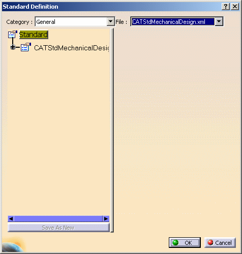
From the file list, select the CATStdMechanicalDesign.xml file to display the default visualization properties defined by your administrator.
-
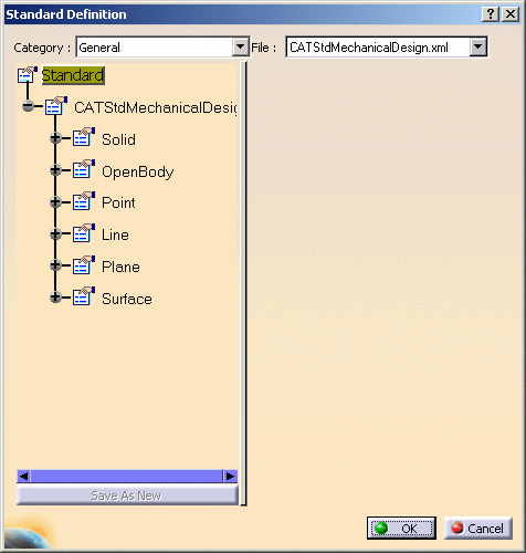
Click the plus sign next to CATStdMechanicalDesign node then repeat this step for each node to display the complete xml tree structure. As you can see in the dialog box below, standards can be defined for Solids, OpenBodies, Points, Lines, Planes and Surfaces:

-
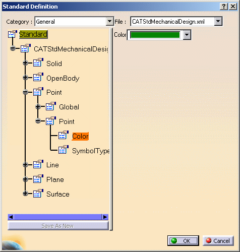
Select the desired item in the tree to expand the node then select the desired element to display the corresponding values on the right.
In our example, we display standards applied to the point default color but you can display standards for all 3D elements such as line type, thickness, etc.
The interactive standard editor shows that the default color for points is green which means that in any new document you will create, points will be created with a green color. -
Click OK to close the interactive editor.
-
Suppose you create a new part document by clicking New
 or by selecting File > New.
 Standards impact new CATPart documents only. They do not apply to other documents you may have previously created.
For detailed information on document creation, refer to Creating New Documents in this guide.
-
Select Start > Shape Design > Generative Shape Design.
-
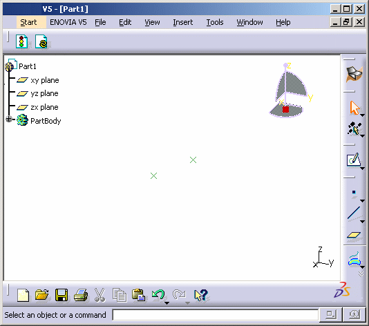
Create as many points as you wish by clicking the Point icon then entering the desired coordinates:

The color of the created points matches the color displayed in the interactive editor.