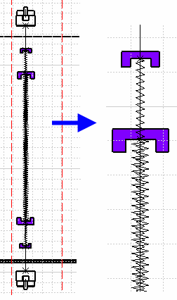
- You can create and apply your own line type standard
- Add 2D details at ends of protective coverings.
When generating drawings, these elements are managed via generative view style parameters.
-
First you must create your own line type standard and save it in the Linetype list available in the Tools > Options.
-
Sample 2D details at ends of protective coverings can be found in the drawing catalog CATDraw2DElectricalDetail.catalog. To take this catalog into account when generating your drawing:
Open the Tools > Options... menu, then in the Equipment & Systems > Electrical Harness Discipline category, select Electrical Harness Flattening
Add catalog
../online/ehfug_C2/samples/GraphicReplacement/CATDraw2DElectricalDetail.catalogto the electrical drawing catalog list.
![]()
Open the
Protective_Tape
CATPart and switch to Electrical Part Design
![]() .
.
-
Click Define Protective Covering
 then select the protective covering in the geometry area.
The Protective Covering Definition dialog box displays: 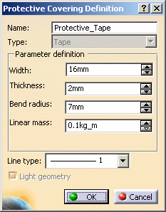
-
In the Line type list, select the line type (the line number) you created in your line type standard, for example 20.
-
Click OK to validate.
-
Identify the 2D detail to be used at ends of protective coverings:
-
Right-click the protective tape in the specification tree and select Properties from the contextual menu.
-
Click More... in the Properties dialog box.
-
Select the Electrical tab and enter the name of the 2D detail in the drawing catalog in the External Reference field.
-
Click OK when done.
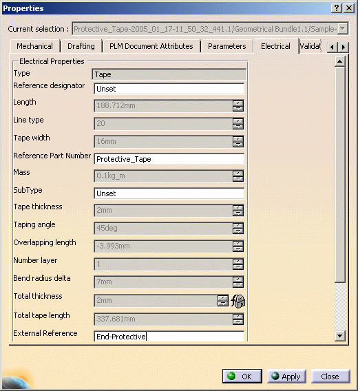
Note: External Reference is a property of the reference that you will store in your catalog then instantiate (place in context). -
-
Save the modified document and then add the protective covering to your working catalog (identified in Tools > Options > Equipment & Systems > Electrical Process Interfacing tab) using Store Device
 .
. -
Open the Sample-Protection and switch to Electrical Harness Assembly
 .
. -
The Instantiate Protective Covering dialog box opens: 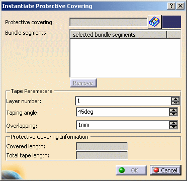
-
Click Catalog
 next to the Protective covering field.
-
Select your working catalog (identified in Tools > Options > Equipment & Systems > Electrical Process Interfacing tab) and then select the previously modified protective covering.
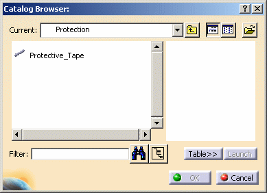
-
Click OK to validate.
-
-
Select the bundle segment.
-
Double-click Start Extremity and set a ratio of 0.1 in the Create Point on Curve dialog box, then click OK.
-
Double-click End Extremity and set a ratio of 0.1 in the Create Point on Curve dialog box, then click OK.

-
Click OK in the Instantiate Protective Covering dialog box to validate.
Your protective covering is instantiated.
-
Repeat to instantiate a second protective covering setting the ratio from both ends of the bundle segment at 0.2.
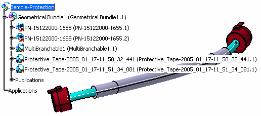
-
Select Adjust
 and tell the system the order in which protective coverings are placed
over the bundle segment:
and tell the system the order in which protective coverings are placed
over the bundle segment:-
Select the outermost protective covering.
-
Select the innermost protective covering.
Protective coverings are adjusted and the system knows which is the innermost and which the outmost layer.
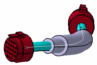
-
-
Save your work.
-
Create a new Product and switch to Electrical Harness Flattening.
Keep the Sample-Protection opened.
-
Click Harness Flattening Parameters
 ,
then click OK in the dialog box that opens to specify harness
flattening parameters.
Note: Drawing parameters will be managed via a generative view style. -
Save your document.
-
-
Select the geometrical bundle of your Sample-Protection product.
-
Save your extracted document.
-
-
The Flatten dialog box opens:
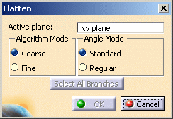
-
Select the geometrical bundle and click OK to validate.
The result looks like this: 
-
Set options to activate generative view style parameters when generating your drawing:
-
Select Tools > Options > Mechanical Design > Drafting > Administration
-
Click to clear the Prevent generative view style creation option.

-
Click OK when done.
-
-
Set generative view style parameters to take into account the different line types for as well as the 2D details on ends of protective coverings.
GVS_sample_2.xml contains appropriate parameters for line types and 2D details. - Copy the
.../online/ehfug_C2/samples/standard/generativeparameters/GVS_sample_2.xmlto the location defined by environment variableCATCollectionStandard.
For more information, see Integrating Generative View Style (GVS).
- Copy the
-
Open a new drawing document using File > New...
The New Drawing dialog box opens: 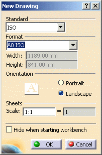
-
In the Standard list box, select the standard specified by the CATCollectionStandard variable you created and validate.
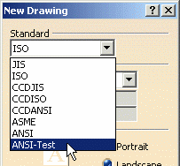
See also remark on linetypes and drawings -
Select GVS_sample_2 in the Generative view style dialog box list that appears.

You are prompted to select a reference plane on the 3D geometry.
-
Click a plane in the flattened document.
The drawing updates according to this choice:
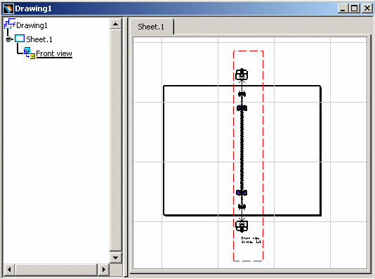
You can see that the protective covering is represented by the created line type and ends are managed as 2D details.
The system maps the appropriate line type in the standard to each layer of protective covering using a simple formula:
Line type used = line type selected in the Protection Definition dialog box + layer number
For example: if you select line type 20 from the line type list in the Protection Definition dialog box, layer 1 will have line type 20, layer 2 line type 21 and layer 3 line type 22.
|
|
