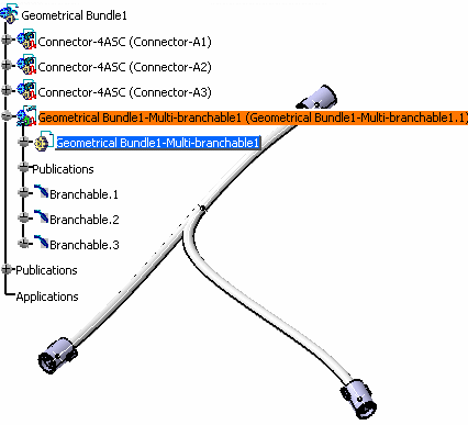
The document now contains a bundle segment.
You are in the Electrical 3D Design Assembly workbench.
![]()
-
Click Split
 in the assembly workbench.
You are prompted to select the bundle segment you want to split. -
Select a bundle segment, then select another point on the bundle segment to locate the reference and split points:
The split point is highlighted and the Split dialog box opens: 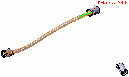
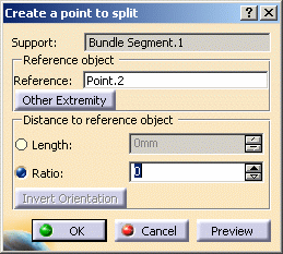

- CATIA creates a reference point and locates both the reference point and the split point at the bundle segment end nearest your second selection.
-
Click Other Extremity in the dialog box to locate the reference point at the other end of the bundle segment.
-
Move your cursor over the bundle segment to relocate the split point.
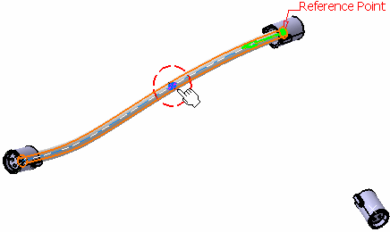

Note: As you do so, distance values in the dialog box are updated. You can also enter a ratio or a length in the dialog box to define the distance of the split point from the reference.
-
Click OK to validate:
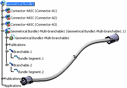
The bundle segment is split in two and a new bundle segment is created. - Tangent continuity between bundle segments is maintained.
- The two bundle segments, each have their own curve and parameters such as bend radius, diameter, etc. They can be edited separately.
 |
|
|
|
|
- Click the Multi-branchable Document command in the Electrical 3D Design Assembly workbench to switch to the Electrical 3D Design Part workbench.
- Click the Branch Definition command to define bundle segment parameters
- Route the bundle segment.
