You have switched to the Electrical 3D Design Part workbench.
-
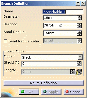
The dialog box opens: 
-
Enter a value in the Diameter field. The Section is automatically computed.
As an alternative, you can enter the Section, the Diameter will be computed.
The bend radius must be at least equal to the Diameter value to insure the correct bundle segment route computation. A message warns you if it is not the case. -
Enter a value for the Bend Radius.
The Bend Radius is the minimum bend radius allowed for the bundle segment.
As an alternative, you can select the Bend Radius Ratio option and set the ratio: the Bend Radius is automatically computed. -
Select the Mode:
The different options are: - Slack:
the bundle segment length is increased by the percentage indicated in the Slack(%) field. The Length field is disabled. - Length:
the bundle segment length is indicated in the Length field. The Slack(%) field is disabled. - Bend:
the bundle segment length corresponds to the minimum distance between the points defining its route. The Slack(%) and Length fields are disabled.
At this stage, the bundle segment parameters are defined.
You now need to route the bundle segment to be able to complete the definition: through this operation, you will create the geometrical representation of the Flexible Curve.
Note that OK and Apply are deactivated. - Slack:
-
See the next task which explains how to route the bundle segment according to the geometrical constraints.