- Positioning the Sketch
- Creating the sketch
- Constraining the Sketch
- Generating a Pad
- Creating a Pocket
Positioning the Sketch
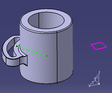
-
Select Positioned Sketch
 in the Sketcher toolbar.
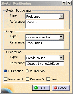
The Sketch Positioning dialog box is displayed. -
Keep the Positioned option selected.
-
Select Plane.2 either from the specification tree or the geometry area.
-
Specify the reference plane for the sketch as shown here.
The Reference field now indicates the reference plane and the Type fields of the Origin and Orientation areas are now activated. -
Select Curve intersection in the Type field of the Origin area.
-
Select the part cylindrical surface to make its axis intersect with the absolute axis origin.
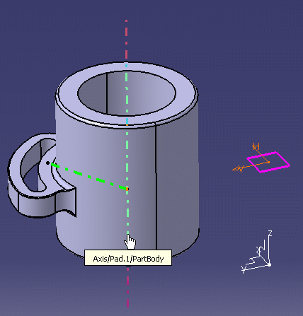
-
Select Parallel to line in the Type field of the Orientation area.
-
Select the Output as shown here.
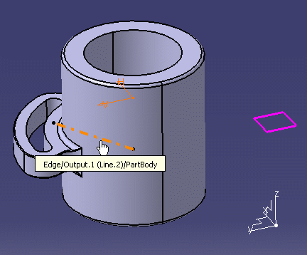
-
Click OK.
Creating the Sketch
You get automatically in the Sketcher workbench and you are ready to sketch a profile.
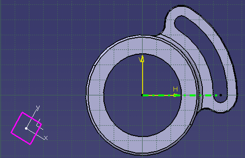
-
Click Axis
 in the Profile toolbar.
 -
Create an axis as shown here.
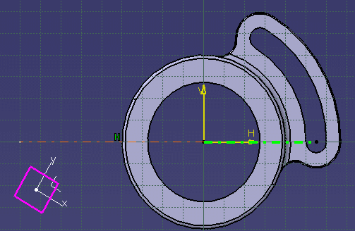
-
Create a circle.
-
Click Profile
 in the Profile toolbar.
 -
Start drawing the profile in order to get a sketch like the one shown here.
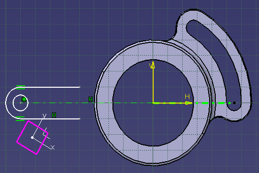
To create the arc of circle using Profile
![]() ,
simply keep holding the left mouse button between the arc of circle first
and endpoints.
,
simply keep holding the left mouse button between the arc of circle first
and endpoints.
Constraining the Sketch
-
Multi-select the arc of circle center and the circle.
-
Click Constraint Defined in Dialog Box
 in the Constraint toolbar.
The Constraint Definition dialog box is displayed.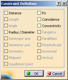
-
Select Concentricity in the dialog box.
-
Click OK.
The constraint has been applied as shown above.
Generating the Pad
-
Click Exit Workbench
 in the Workbench toolbar.
You are now back in the Part Design workbench and the sketch is displayed.
-
Click Pad
 .
.
The Pad Definition dialog box is displayed.
-
Enter 10 in the Length field.
-
Right-click in the Selection field and click Go to profile definition contextual command.
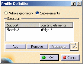
The Profile Definition dialog box is displayed.
-
Select Edge.3 from the geometry area.
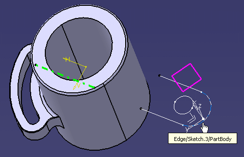
The Profile Definition dialog box is updated with the selected sketch.
-
Click OK in the Profile Definition dialog box.
A warning dialog box is displayed to inform you that the profile is not valid.
-
Click OK in the Warning dialog box.
-
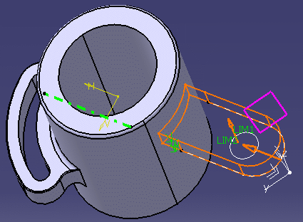
Click the Reverse Side command to change its direction and solve the problem.
The profile is displayed as shown here. The normal is now well positioned.
-
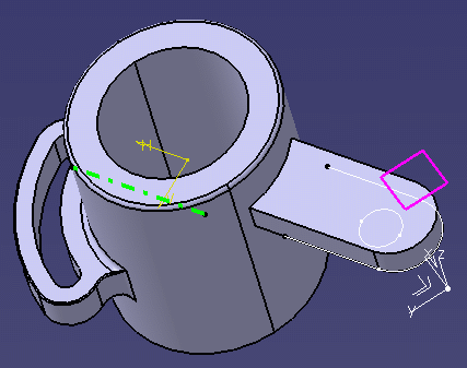
Click OK in the Pad Definition dialog box to validate the pad creation.
Creating a Pocket
-
Click Pocket
 .
.
The Pocket Definition dialog box is displayed.
-
Right-click the Selection field.
-
Click Go to profile definition.
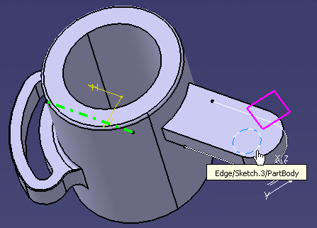
The Profile Definition dialog box is displayed.
-
Select the circle from the geometry area.
-
Click the arrow to have it displayed upwards.
The Profile Definition dialog box is updated with the selected element.
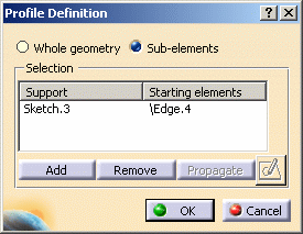
-
Click OK in the Profile Definition dialog box.
The Pocket Definition dialog box is displayed back.
-
Keep the Up to Last option selected.
-
Click OK in the Pocket Definition dialog box to validate the creation.
The pocket is created as shown here.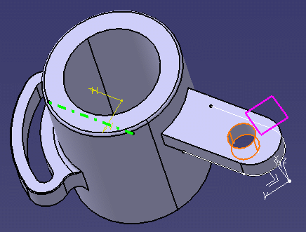
- The pad has been created and its lines have been automatically trimmed so that it is tangent with the first part.
- To have more details on the Sketch positioning option see Creating a Positioned Sketch.